A quick write-up of my Wavepro 7200A restoration and uphack. I bought this one from Ebay after low-balling the seller:

The description said the display wasn't working. Besides that it is clearly visible the bezel is completely ruined. When it arrived it was time to take it apart.
First let's see if there is some life in it. An external monitor showed the scope booted but no image on the internal display. For good measure I replaced the CCFL backlight of the display with LED backlight. For that I had to remove the video driver board to solder some wires to it because I needed to get 12V from somewhere.


That also leads to the discovery of several design flaws in the hardware. Look at how the metal washers are over the traces:

And the top cover also serves to keep the acquisition board in place so whatever forces comes down onto the top cover is directly transferred onto the PC motherboard:
Really??

The bezel was broken in several pieces. Some PVC glue and tape on the inside helped to put it back together:

Unfortunately to bottom part is strained a lot and it was broken in several places. I had to glue in a brace to keep it together. After that it turned out there was also a crack in the corner which needed glueing as well. For these jobs I use masking tape to keep the parts together while the glue cures.

Back to some testing... the hard drive seemed to have a problem so I went for a reinstall of Windows XP and the LEcroy software on an SSD. The software is downloadable from LEcroy so no problems there. That worked OK but channel two had issues which caused the scope to halt and lots of relays clicking. Time to take the acquisition board out... Well... hello!

For good measure I swapped the input module from channel 2 with the auxilary channel. One of the nice things of these scopes is that they have 5 identical input modules so you always have a spare

Getting the module wasn't easy because the standoff underneath the module unscrewed itself pushing the module up. As a last ditch attempt I tightened the screw further and after that the standoff stayed put. After swapping the input module I had 4 working channels. It is possible to use the auxilary channel as an input for channel 3 and that seemed to work fine. The issue with channel2 was likely contact related.
Now onto the display... The display system relies on an Intel proprietary AGP slot extension which outputs display data for use with a TFT screen. The video board in turn converts this to the right signals to drive the TFT screen. After some measuring it turned out the driver board wasn't getting any input signals from the AGP slot. After cleaning the AGP slot using a piece of card board to scrub the contacts the display works again.
Next stop: PC upgrades. I ordered two 1GB Kingston PC3200 memory modules from Ebay as NOS. I contemplated to buy a 3.2GHz processor as well instead of the existing 2.8GHz 533MHz FSB processor but decided to go through my old PCs first. I found a 2.8GHz P4 with an 800MHz FSB in an old Dell PC and decided to put that in and transplant the Dell cooling solution too because it is very quiet. I had to take the motherboard out for this job though. The CDROM drive no longer fits together with the cooler. Since the motherboard can also boot from a USB stick that isn't a really big problem.


Something else I noticed is that the fans are
LOUD. Let's do something about that! This website put me on the trail of 'Gentle Typhoon' fans:
http://s-audio.systems/blog/lecroy-upgrade/These are obsolete but I managed to procure the ones mentioned (D1225C12B6 and D0925C12B4). I also wanted to keep the plugs as original as possible. It turns out the original fans use Molex Spox connectors so I ordered some contacts and housings. I have the Molex crimper for it anyway. With the D1225C12B6 the temperatures where a tad high so I went one step up in power and used the D1225C12B7 version which keeps the temperatures similar when using the original fans.

One problem was that the CPU fan wasn't showing the RPM with the yellow wire connected. I didn't measure any pulses on it. Can I hack the fan? Yes I can!


It turns out the fan uses a standard chip from Rohm. This chip has two outputs on pins 15 and 16: rotor lock and RPM. R11 and R10 select between which one is connected to the yellow wire. Moving the resistor from R11 to R10 got me the RPM output.
Last but not least I decided to rotate the fan on the CPU cooler 90 degrees so it blows the air outwards so the hot air doesn't go into the acquisition board.

With the original fans I measure 75dB at 25cm from the front using a mobile phone app. With the fan replacements the sound level is at 68dB. Also the 'Gentle Typhoon' fans seem to be designed to produce a pleasant sound. Needless to say the improvement is massive!
Time to fit the SSD onto a bracket. I looked up the mounting dimensions for 3.5" and 2.5" drives and drilled some holes into an aluminium bracket which I created from a piece from my 'bits of metal' stock. It also needed milling a slot into it to make it fit.
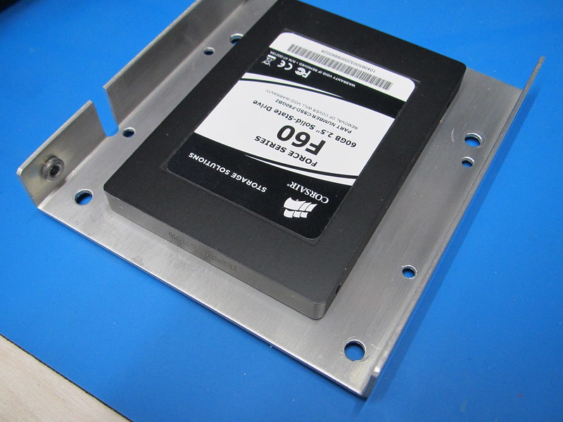

Fortunately there are SATA connectors on the motherboard so fitting a SATA drive is easy. It also gets rid of a lot of cables.
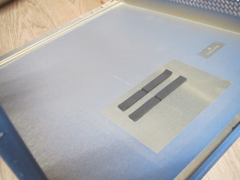
Then the last bit... uphacking! A fellow forum member was so friendly to share his tricks to turn a 7200A (2GHz) into a 7300A (3GHz). What it takes is removing some capacitors (marked red) and replacing resistors with 0 Ohm links (marked blue):
")
A software key does the rest to make the scope think it is a Wavepro 7300A.
All in all a nice addition to my lab. Finally! My first real Lecroy scope. I think I'll need quite a bit of time to go through all the possibilities this oscilloscope offers. Lecroy typically is strong where it comes to signal analysis and math.


