Part 2 - So, enough with mechanical stuff. How well does it work?
There's lots of output combinations (read the spec sheet in the previous post), but I thought I would set up the highest current and highest voltage configurations. Here's the max current config driving an Array DC load. The MX100 has its outputs paralleled and is outputting 16V @ 15A. You can see by the voltage reading on the Array there's a significant loss in the test leads at this current. I could have connected all three sense lines to compensate for this, but I didn't do it in this picture. (The sense inputs work fine; I did try them.)

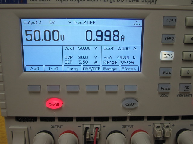
Here's the outputs reconfigured for max voltage 140V @ 1.5A with the three outputs in series:

I found the readback voltage to be very accurate on all 3 outputs. On output #1 it was no worse than a few mV, and most of the time much less than that. Current was similarly accurate to a couple of mA. Output #1 has more precision in setting and readback than the other two, for some reason.
One thing I would have liked to see on the home screen is the watts being supplied by each output. There appears to be enough space for it. But you can still get the reading ("VxA") by pushing the configuration button for an individual channel:
Noise is well within spec, as far as I can determine. It's so low I had to pull out an old Tek AM502 differential amplifier. The limit on this amplifier is 1MHz and not 20MHz, which is how power supplies are usually specified, so take it for what it's worth. Here's the MX100 (output #1) compared to the E3631A (6V output). The amplifier is set to x1000, so these captures are in mV (not volts). Outputs were set to 5V into a 10ohm resistor. The DC load was not used since those tend to inject noise. The MX100 internal switcher runs at 100kHz and I was not able to see that frequency in the time domain but it does show up on an FFT (FFT not shown).
Here is the E3631A:

And the MX100:

A quick load response test stayed within a couple hundred mV. Using the DC load to create a 5A 1ms load pulse, here is the output voltage in yellow, current in green. Output voltage was set to 5V.

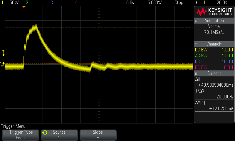
There was some glitchiness when changing ranges on the various outputs. All the outputs had this artifact. It wasn't extreme, and was always around 125mV. Here's an example. The output is loaded with a 10ohm resistor and is configured off.
The unit has a hard AC power switch. Power off could be a little better. Here is turning the AC off with open terminals.

And here it is again, this time with a 10ohm load.

And here is turning the AC power on (the output is configured off), again with a 10ohm resistor.

So, AC power on/off transitions could be handled a little more gracefully, but glitches of a few 100mV isn't likely to hurt anything.
I tried out all the communications interfaces. I use Linux and they all work with Linux. (I'm sure they work with windows too, but don't ask me.) The USB interface appears as an ACM device. RS232 is 3-wire xon/xoff. All remote interfaces are enabled at all times, although there are exclusive lock commands if your application needs it.
It should go without saying, but all interfaces are isolated.
One non-obvious thing is that all commands submitted through USB or RS232 must be terminated with 0x0a. Otherwise the unit will not respond. This is buried in the documentation but I missed it.
Any time a remote commands is submitted, it puts the front panel into local lockout. This is common behavior for GPIB devices, but I wish it could be configured. The alternative is to always send a command to re-enable the front panel.
Firmware upgrades are handled via USB. There aren't any upgrades yet that I am aware of. There are instructions on how to do it from Linux if you don't use windows. Service and calibration documentation will be available, but customer support says it's not done yet.
The unit will respond to commands submitted over a TCP socket, but it also has a web server. The web server will allow you to do basic configuration and status, but in terms of working with the instrument this could use a major amount of work. The only control possible from the web page is to submit text commands using this page:
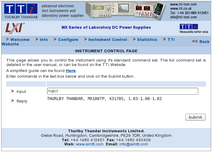
They need to add a *real* GUI with buttons, knobs, real-time plots, and everything that you'd expect from a web interface now-a-days. If I wanted text commands I can already get that from telnet.
The PDF user manual is very well written. There's no sign that this is from another OEM or is a rebadge, but if someone recognizes it please post.
Comes with a printed manual and CD. CD contains the docs and drivers for all TTi products. Drivers: IVI, Labview, LXI, NI, USB, TCP example program. (All useless to me and only adds to my cost.)
I've only had the opportunity to use TTi tech support three times. Once about my iProber, and twice on the MX100 about the calibration/service manual and then about firmware upgrades. The questions were relatively easy, but answers were prompt and complete. So far, so good.
What I like most about this supply is its wide range of voltage and current outputs to fit just about any project. We'll see. I'll post any interesting updates, good or bad, as it starts getting used for real.


