Datron 1071 - A very strange problemAfter fixing the PSU and putting everything back together again, I started testing the meter in earnest to see how accurate and
stable it was. Sadly, I rapidly discovered that it was neither accurate or stable.

The first thing I noticed was that when turned on from cold, there was a huge offset on the voltage ranges. For example, on the
10V range, there was a -700µV zero offset with the input terminals shorted. As the meter warmed up, this would decrease and
sometimes go all the way to a few tens of µV positive, but not always. Once the meter had warmed up, I could use the input zero
key to tune out the offset, but if I connected up a voltage reference for a few minutes and then switched back to a short again, the
zero offset would again be way off. Or sometimes not!
I noticed some white powdery deposits on the analogue board which looked like the result of poor cleaning after the repairs that
had previously been performed, so I took the analogue board out, taped over all the pots to stop anything getting into them and
did the job properly this time. This made absolutely no difference whatsoever. The meter still couldn't establish and hold a stable
zero. In desperation, I powered up the meter, threw a winter coat over it and gave it a thorough roasting in case the instability was
caused by moisture which had infiltrated it. Again, this proved to be a pointless endeavour.

Utterly frustrated, I put the meter away in a corner and forgot about it for a year.

...
The pressure from work had started to abate and I could feel the Datron mocking me from the corner of room. I started again by
studying the service manual's functional description and circuit diagrams in detail. At some point, a lightbulb came on while I was
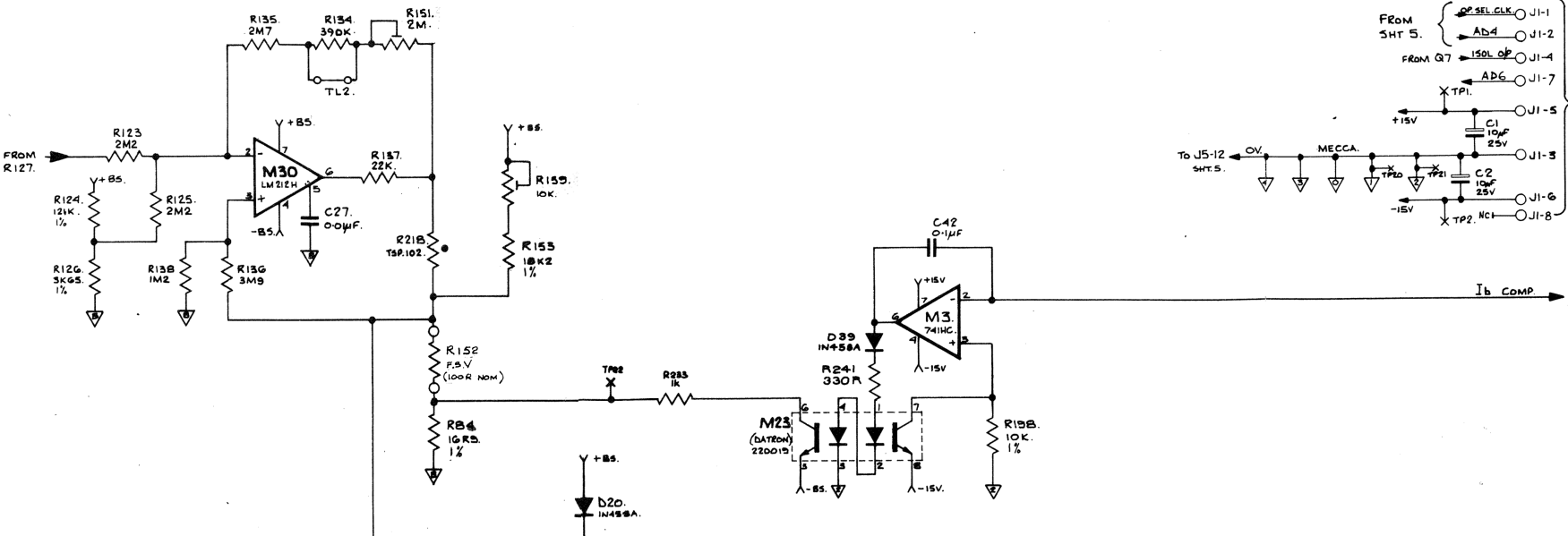
looking at this part of the analogue board's circuit diagram:

This jogged my memory about an excellent article by a gentleman named Karlheinz on amplifier.cd where he discussed his
experiences repairing a Datron 1061A. (
https://amplifier.cd/Test_Equipment/other/Datron1061/Datron_1061.html)
The circuit in the diagram deals with input bias current compensation. Specifically, when calibrating the meter, one step of the
process consists of connecting a shielded box containing a 10MΩ resistor in parallel with a 1nF capacitor to the input terminals
and pressing the "Ib" calibration button. When you do this, the meter measures the input bias current, calculates a correction
and stores that in the calibration memory.
When a voltage or resistance range is subsequently selected, the digital board fetches the Ib correction value and transfers it
to the analogue board over the opto isolators which implement the isolation barrier between the boards. The value itself is an 8 bit
number which the analogue board then latches into buffers which function as the input to a D-A converter which is implemented
in discrete components on the analogue board.
The voltage generated by the converter enters the circuit pictured above on the Ib Comp line and is applied to the inverting input of
op-amp M3. This causes the op-amp to drive current through the diode and resistor to the M23 opto isolator's LEDs and the right-hand
transistor to sink current so that the voltage over R198 matches the input voltage on Ib Comp. The other transistor acts as a current
mirror referenced to the negative bootstrap voltage (-BS) and effectively floats the Ib correction onto the bootstrap supply. This
mechanism ensures that no cross current can flow and ensures that the DC isolator remains isolated from the correction voltage.
If there's anything wrong with the M23 opto isolator, this circuit won't work properly and could well cause the kind of problems I was
seeing. It wouldn't be the first time a faulty opto isolator has been identified as the cause of a problem in these meters and when you
consider how this opto isolator is being used, both LED/transistor pairs need to have matched characteristics for the correction to be
faithfully reproduced - this particular opto isolator is a specially selected part and is marked with an orange dot.
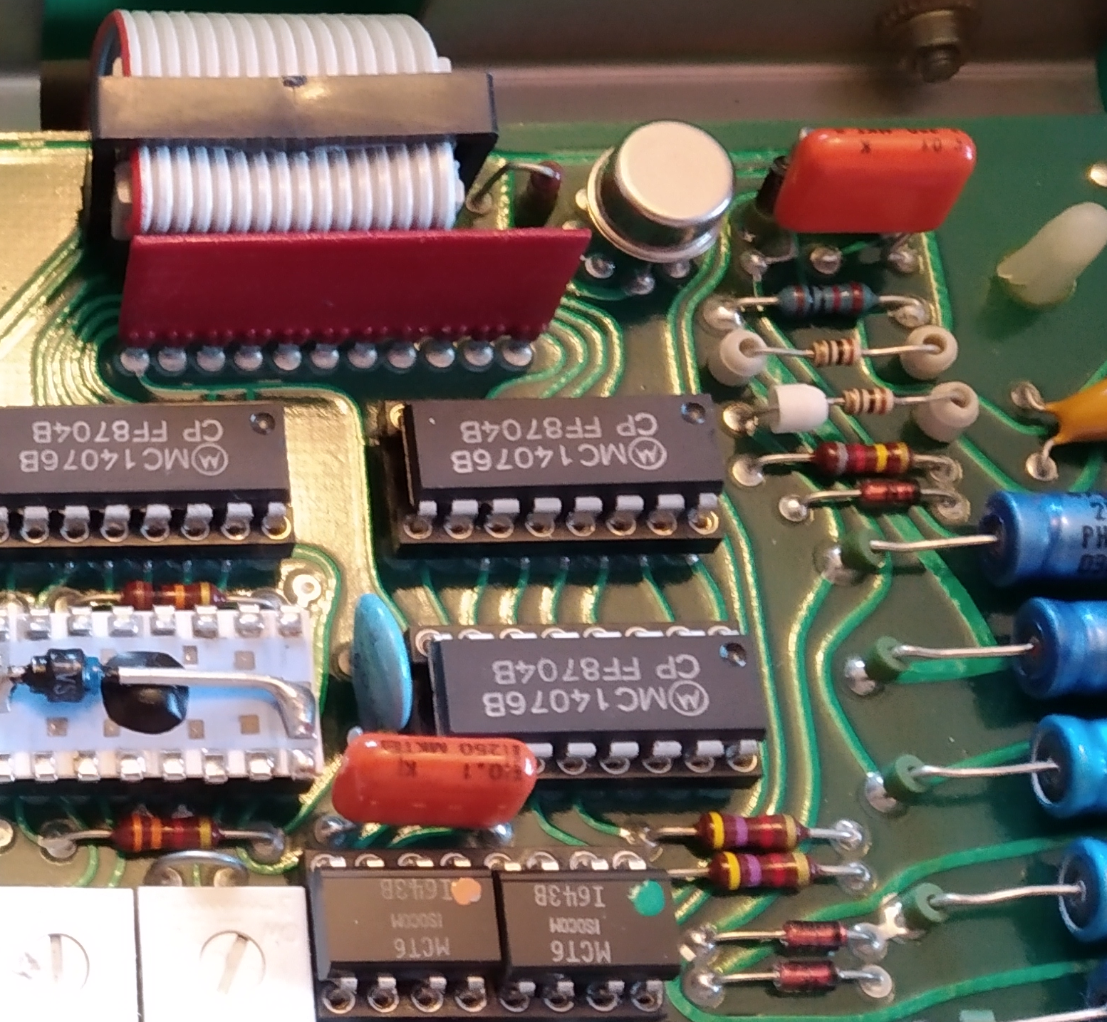
Here is the relevant part of the analogue board:

The opto isolator M23 is the 8 pin part with the orange dot at the lower left of the photo and the op-amp M3 is in the TO-99 package
at the top of the picture to the right of the flatflex cable.
Armed with the location of the components involved, I fired up my oscilloscope and prepared to start probing!
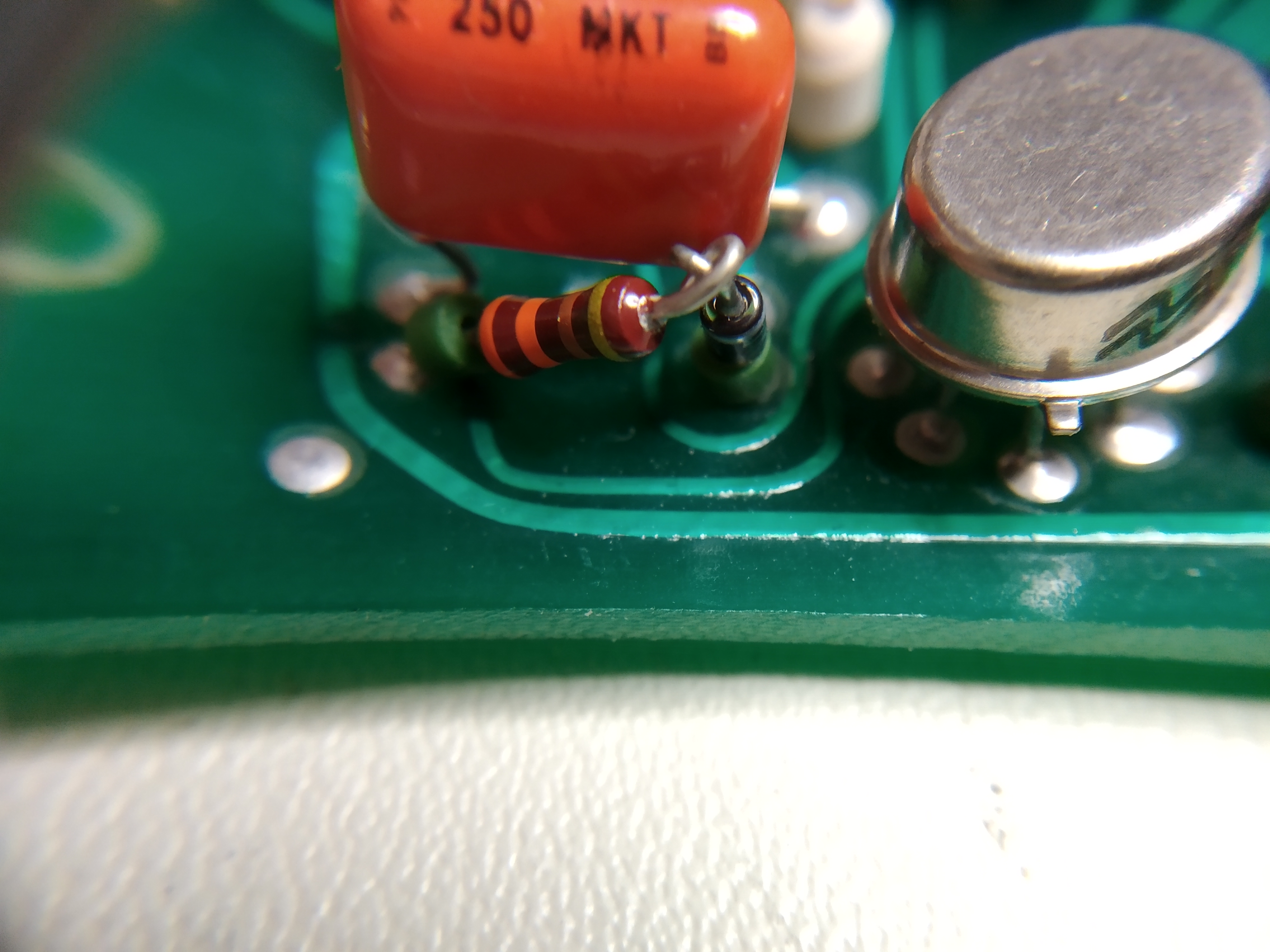
The diode and resistor that pin 6 of the op-amp is connected to are just behind that red film capacitor next to the op-amp. You won't
believe what I saw when I looked behind that capacitor...


Whoever built the PCB in Datron's factory had obviously twisted the component leads of the diode and resistor together in preparation
for soldering them but had gone to lunch or been otherwise distracted before they completed the final step! And so the board remained
for some 35 years before the connection between the two components deteriorated to the point that it started to cause a problem!
Due to them being hidden behind the film capacitor, I never noticed and neither did anyone else. I'm sure the connection was perfectly
OK during QA testing and calibration, so it just sat there like a little time bomb waiting to trigger decades later.
I gave the leads a gentle scraping with a scalpel and used plenty of flux when I finally completed the forgotten assembly step so I could
be sure that the connection would be good after soldering. I then constructed the suggested "Ib source" required and performed the
calibration step. The meter's zero offset immediately dropped to zero. After turning the meter off and allowing it to cool down before powering
up again, the initial zero offset was within a few tens of microvolts and once the meter had fully warmed up, it was very close to zero without
needing the use the "Input Zero" button.
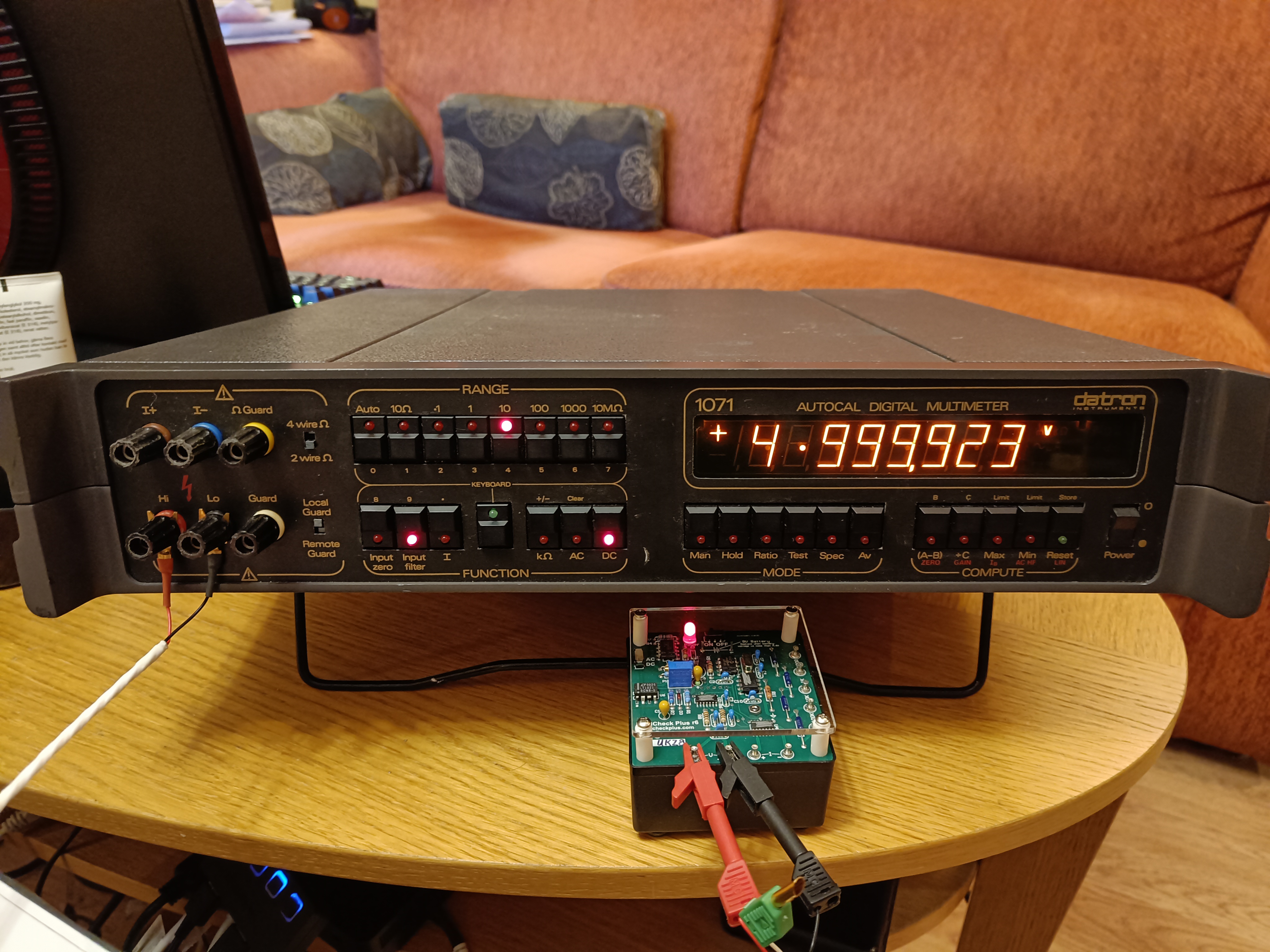
Since correcting this problem, the meter has proved to be exceptionally quiet, stable and accurate. Noise on the 10V range is around +/- 2.1µV
which beats my Solartron 7061 (at +/- 12µV) by miles. Both meters agree within a few PPM on any reading which is excellent considering that
I paid to have the Solartron properly calibrated couple of years ago.
And finally, it's just a great looking meter!
