So, its test it thursday: Update from the "Fun with (Ice-)TEA" dept.
One of the key features of a precision power meter is phase alignment between voltage and current over a wide frequency range.
If you're measuring power at an phase angle near 0°, a small phase deviation between voltage and current will cause large errors in Q (reactive power).
The other way 'round, if you're measuring near 90°, the real power will be near zero while there might be quite large reactive power, and small phase errors will cause large errors in real power (P).
Every half-decent power meter does the real power calculation by multiplying u(t) by i(t) and integrating the result over a multiple of input period time. Calculation of Q might depend on the actual implementation or might not be available at all.
So for my tests, it was the natural choice to conduct the measurements at 90° phase between voltage and current over a large frequency range.
This is the first setup:


The dual channel AFG provides output signals at 90° phase. One channel is fed directly into the voltage path of the instruments. The other is routed through the high speed amplifier and a 50 Ohm load resistor into the current measurement paths. The dummy load resistor provides non-reactive response to a few MHz, it's not that good but good enough for this test.
DUT are the WT1600 and the Clarke-Hess model 2330 power meter.
This is the plot from 10Hz to 800kHz, read out real power of these instruments. Apparent power seen by the meters is about 1.27VA during the tests. Calculating errors is left
to those playing along at home as an exercise to the reader, I've attached a text file with the raw values. You've got to look up these attachments at the other thread:
https://www.eevblog.com/forum/testgear/yokogawa-wt1600-digital-power-meter/msg4184464/#msg4184464
Next one, the WT1600 vs. the Voltech PM3300:


Last, but not least: WT1600 vs. Tek A6302 plus AM503 and RTB2004 Math and Measurement features:


Note:
The NF 4005 amplifier has a specified frequency response to 1MHz, so one has to expect more or less relevant phase errors at frequencies above maybe 200kHz. So I don't know wether the -0.7W deviation at the end of the frequency axis (800kHz) is caused by the power meter or by the amplifier / dummy load.
At least all the power meters agree to some degree, so this points to the amplifier causing the phase shift, otherwise the Tek current probe and the scope should have enough bandwidth to not cause a significant error here. I haven't investigated why the phase shift at this combo is into the other direction (positive real power displayed instead of negative).
I've deskewed the current probe vs, the voltage channel, so I'd put some trust into the scope measurement, otherwise it's the only measurement that largely disagrees with the power meters ...
So no idea ATM which one is more correct.
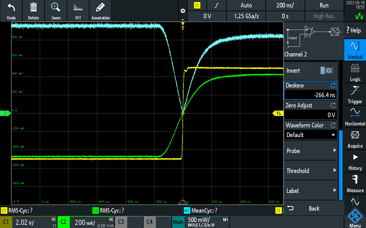
Edit / P.S.: Now that I'm looking at the finished post, it's quite obvious I did the deskewing wrong, leading to a phase lead at the current probe / scope setup. So it's this last measurement that's lest trustworthy.


 Topic: Test Equipment Anonymous (TEA) group therapy thread (Read 18110587 times)