This installment will complete the compensation adjustments on the CA plug-in.
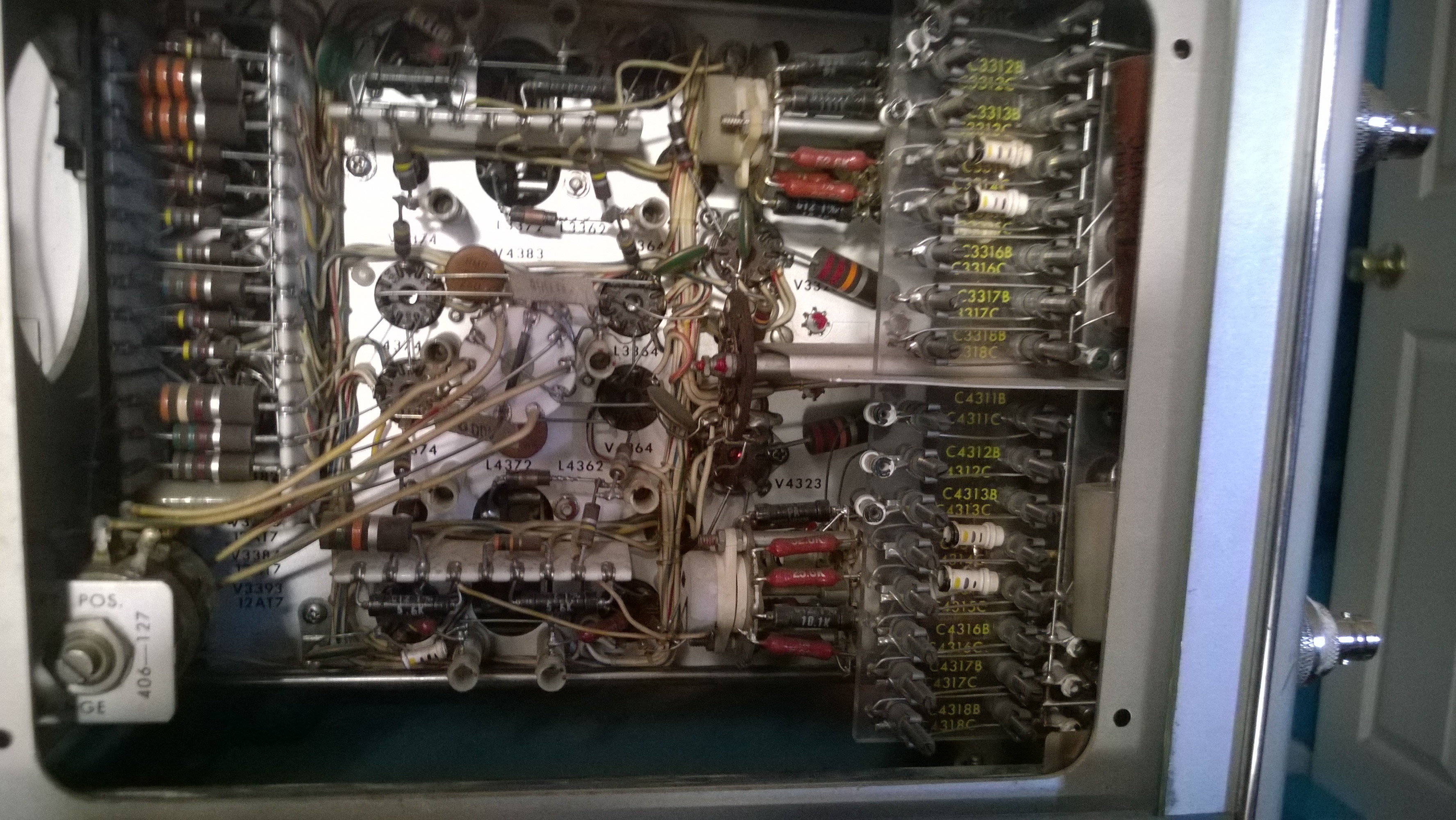
Here's an internal view of the CA plug-in. The compensation variable capacitors are all neatly arranged on the far right in a row. Channel A top, channel B bottom.
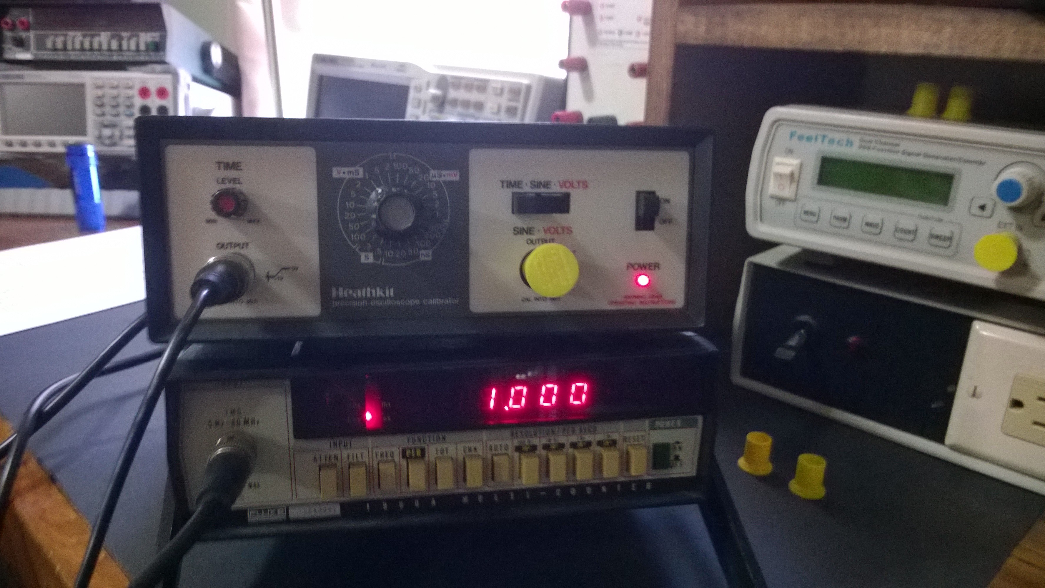
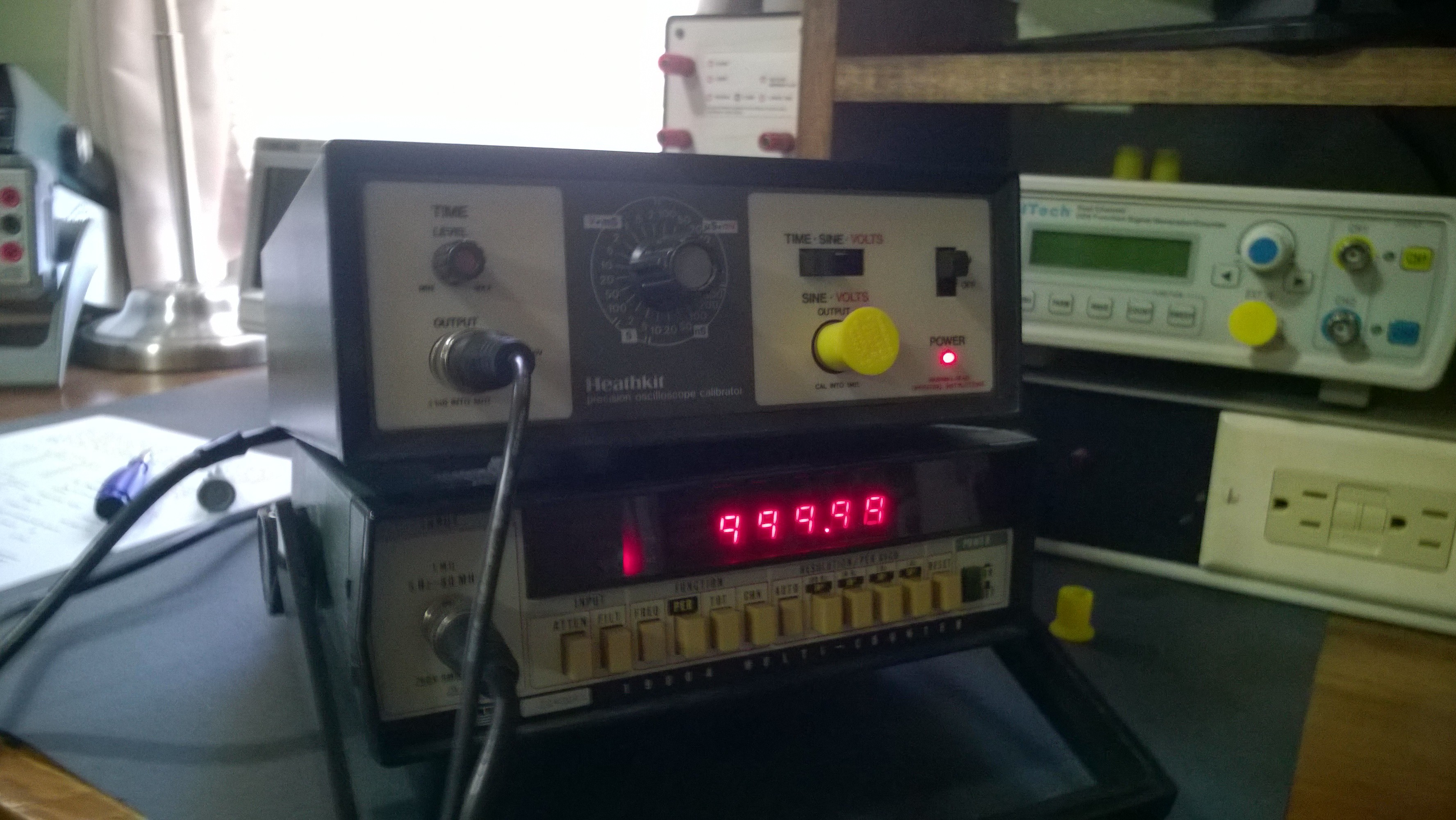
The test set up. Heath IG-4244 Scope Calibrator set to fast rise time 1Khz square wave and the Fluke 1900A Frequency Counter connected to the 535A Vertical Signal Out as a monitor.
Of all the attenuators the only one was slightly off. Channel A, 0.5V/div.
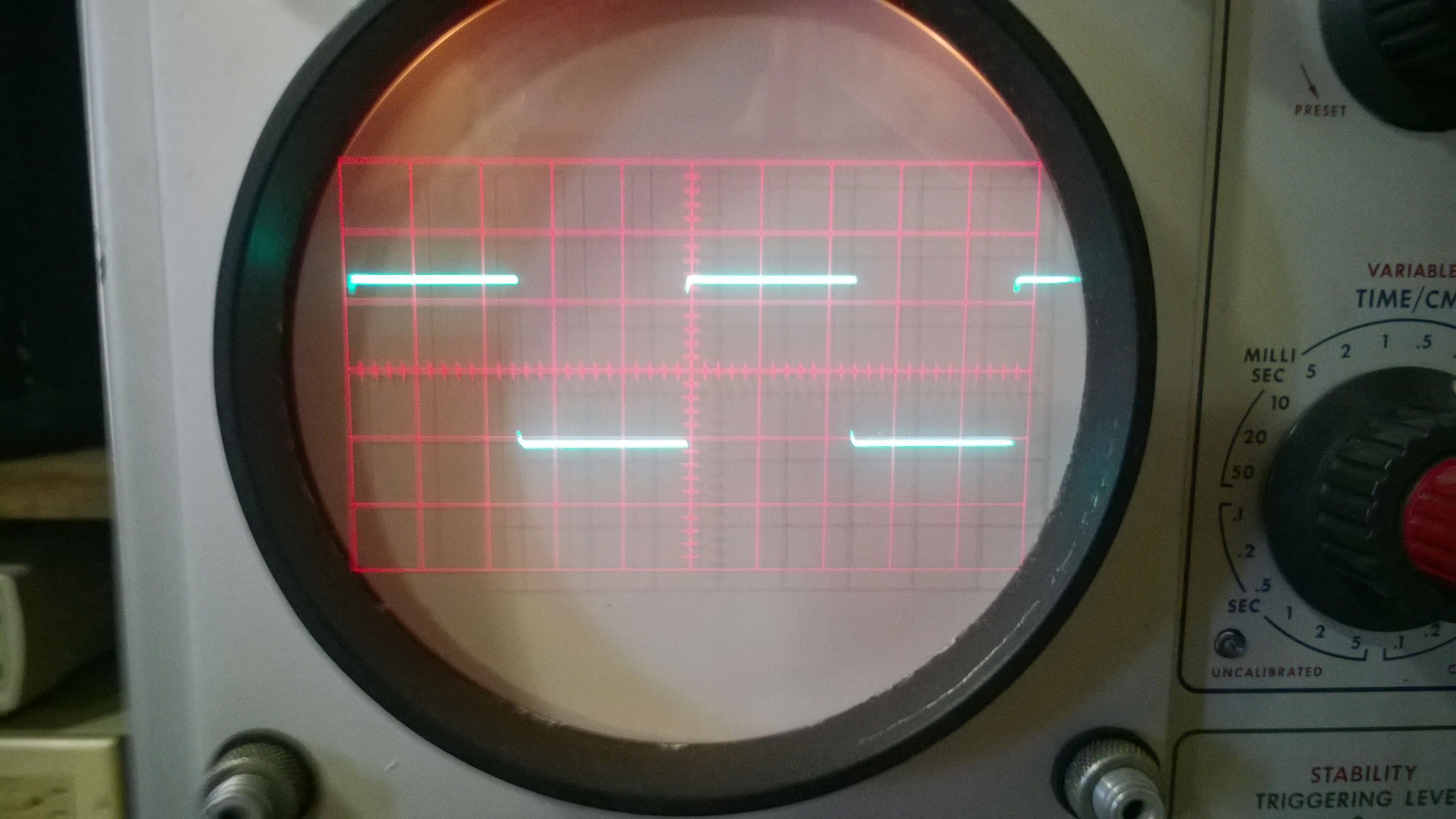
Fixed.
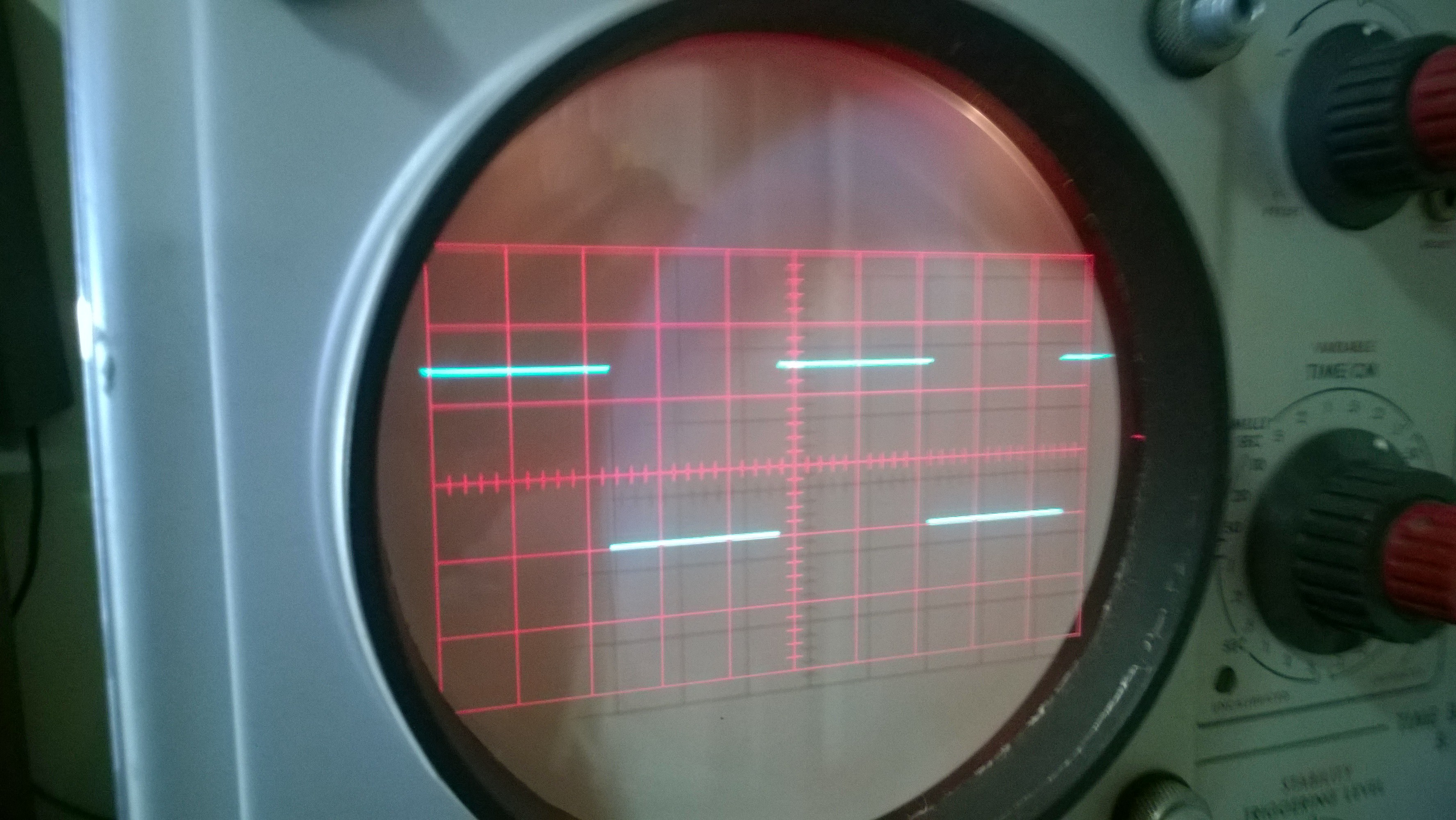
Now the IG-4244 set to 1MHz.
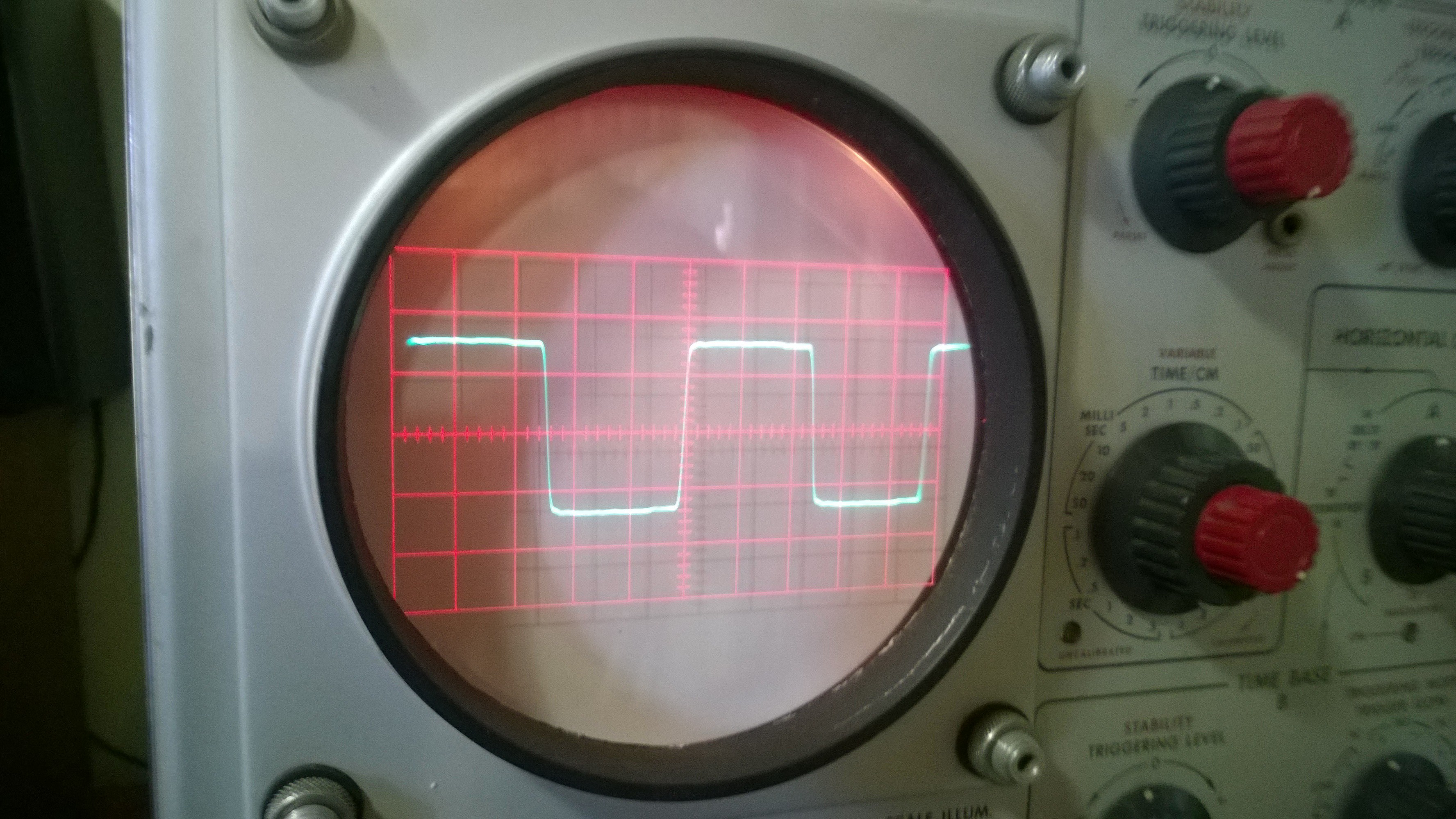
Amazingly good 1MHz waveform. The bandpass of the CA plug-in is 27MHz while the 535A is only 15MHz. So the 535A sets the total system response.
Next up......a more involved frequency response check.


