-
Here's some softcore Tek pern for ya....

I'm about to dig into this 475 vertical calibration, find and replace the faulty ceramic trimmers, then calibrate the vertical and adjust the other circuits as needed.
Today is my last day off for the next two weeks so I'm hoping to get it finished up today.
That’s begs a question: what’s a group of tektronix scopes called? Herd, gaggle, flock? -
Here's the B&K 3010 Function Generator pron. It powered up fine and was working for about 5 minutes then it quit. No smoke...just quit. So I'll have to get a schematic and figure out what took a dump.
And the case.....it's the same shitty beige as the Fluke cases. It's gonna get painted.

-
That’s begs a question: what’s a group of tektronix scopes called? Herd, gaggle, flock?
I call mine the "Tek Tribe"

-
That’s begs a question: what’s a group of tektronix scopes called? Herd, gaggle, flock?
I might as well call mine "The Tek Horde", since it can easily be confused with "hoard". If you ask my girlfriend, I'm hoarding gear, so it's definitely fitting!! -
Here's the B&K 3010 Function Generator pron. It powered up fine and was working for about 5 minutes then it quit. No smoke...just quit. So I'll have to get a schematic and figure out what took a dump.
And the case.....it's the same shitty beige as the Fluke cases. It's gonna get painted.
What's Q12's deal? He's looking at me funny. I don't know if it's the ol' stink eye, goo, or if he's melting.
-
That’s begs a question: what’s a group of tektronix scopes called? Herd, gaggle, flock?
A struggle. -
We have a winner!

-
That’s begs a question: what’s a group of tektronix scopes called? Herd, gaggle, flock?
A struggle.
That's just mean, man...
-
OK, the Heath DMM settled out at 9.9V after about an hour. And a quick check of the Ohms showed it needed touch up too.
Pulled the back off and was greeted with this. But at least all the calibration adjustments are right there. One for DCV cal and a bunch for each ohms range. I have to let it cook again for a while then I'll calibrate it.
This my friend is how you stuff 5 pounds of shit into a 2 pound bag. This mofo is absolutely jam packed.

-
That’s begs a question: what’s a group of tektronix scopes called? Herd, gaggle, flock?
A 'sweep', obviously... -
Here's the B&K 1801 Frequency Counter. Just powered up. Not bad. Will let it settle for a while. I'll show pron later.
I'm liking those LED's.
-
After spending a couple more hours on trying to get the 2831D close to spec, it appears repairing it will be way more trouble than it is worth. All of the power rails but one are out of spec by at least ten percent and two of them are directly used as voltage references in addition to supplying power to the circuit.
 Plus the schematics, in addition to being incomprehensible don't actually match the circuit.
At this point the slope of the time required versus the value generated curve has turned negative. Going to put the cover back on and send it on its way.
I should have known better. I didn't do any testing of it before I bought it because... it was a bargain.
-
Acronyms - the brown paper bags for Americans for nasty expressions.
Surf around on that Urban Dictionary website if you want to get the full scope of the nastiness from the nastiest of the nasty yankees!!
That is, sadly, the absolute & unvarnished truth.
mnem
I take pride in being a "Damned Yankee"; but only in comparison to southern-fried assholery, where they smile sweet as honey all the while selling you and your children down the river... -
This late SN 475's transient response is looking pretty scruffy..
(pulse from 106 through tunnel diode pulser)
-
This late SN 475's transient response is looking pretty scruffy..
(pulse from 106 through tunnel diode pulser)
That's not that bad. I'd consider it "good enough"
-
Interesting. Looks like there's frequency compensation present on the CC and CV opamps. The design is a little weird though as the entire thing is referenced to the adjustable rail after current sampling rather than a low impedance ground. I'd start by trying to slow the driver transistor down T1/T101 with a bit of miller capacitance and see it that responds.
Edit: Previous attempts to design power supplies myself have always resulted in a monumental effort on stability! Diagnostics usually involve fecking around for hours measuring sampling vs control voltage phase shifts and trying to get that loop stable at all frequencies. LTspice only gets you 80% of the way there. One I did which was a simple diff amp with a couple of 2n3904's was only stable when it was a warm day. Fixed with a bit of heatshrink over the two transistors! Makes you appreciate the effort HP put into their linear supplies over the years even if they did feck up a bit with the E36xx
Edit 2: actually a mini rant. You see loads of crappy power supplies described all over the internet and in electronics magazines. They worked for the author, precisely once under one set of load conditions.
Here is a screenshot of the oscillation.
The PSU was set as follows:
- output voltage set to 2V
- current limit around 500mA
- output shortened with a DMM
This was measured at Pin 1 of IC 101.
Here are the schematics as I have them in Eagle:
I'll try the Miller caps on the weekend.
Would it be helpful to increase the values of C3 / C103?
-
The Heath IM-1202 calibrated fine except for the 200K ohm range which is about 600 ohms off. I hit the stop on the cal pot. Not gonna worry about it. This guy is never going to do any serious work.
Here's the B&K Frequency Counter torn down. It's connected to the PCOXO standard and will cook for about 12 hours then I'll adjust it.


-
Remember when mnem was going to send me a B&K function generator and frequency counter? Well today the box showed up. MUCH bigger and heavier than I had anticipated. And no wonder. Look what was inside.
 I guess he wanted to lighten the load to Canada.
Among the assorted parts and odd stuff we have:
B&K 3010 Function Generator
B&K 1801 Frequency Counter
Heath IM-1202 2.5 digit DMM
Heath SG-5240 Color Bar Generator
Texas Instruments TI-95 Procalc (I think that's gonna result in being disowned by Nixiefreqq.)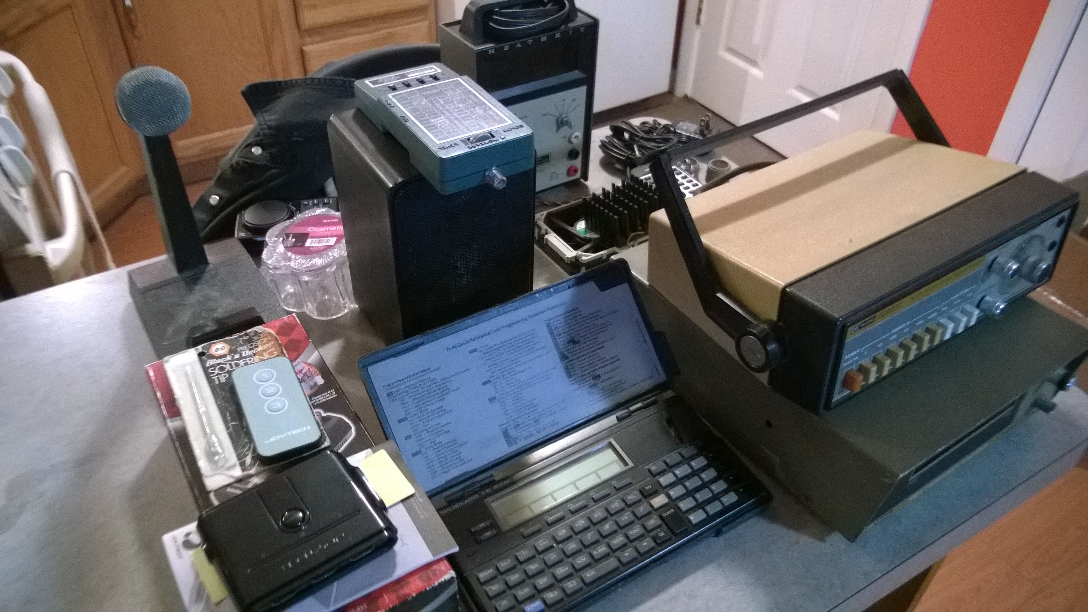 Thanks pal....I'm somewhat dumbfounded at the moment.
Well... it was partly "giving the stuff a good home" as opposed to just Goodwill-ing it where half will go straight into the tip, and partly helping a friend feed his habit in semi-retirement.
The ProCalc... it is actually the oddball of the TI stable; it will think RPN or algebraic depending on the sketch loaded so it is pretty much BI-calcular, plus the inclusion of parens means you can arbitrarily declare order no matter which way it happens to be swinging ATM.
The Shure table mic & Minimus-7 cast aluminum speaker are the last remnants of my radio bench; there was a time when EVERY radio & scanner junkie had one or both as they were a known baseline for quality audio & clarity in spoken voice. That grille will pop right off; it really could use a fresh coat of paint, but I figured you'd enjoy pimping it for yourself.
The Heath gear... I knew it was going to a good home. That was enough. That little pattern/raster generator is just crammed full of 74xxx goodness; I figured if anybody would appreciate it like I did, it'd be you. And the IM-1202... I SWEAR I heard it calling your name from the bin by my bench, no lie!
The Pioneer remotes are much-sought-after, or at least once were among vintage audio peoples. The one is a brand-new "jog-shuttle" model that works with pretty much all Pioneer Laser-Disc players, and the little one is similarly sought after for use with the Pioneer 6-disc cartridge CD players as it has the mini-joystick for menu navigation. I could swear I remember you saying you had one of the two; I figure if you don't, you probably know somebody who can use them.
The rest... well it was as much a matter of "Why fill the space with bubble-wrap when I can stuff it with... STUFF?!?" as anything.
Cheers, and glad you like it all!
mnem
*AWOL from packing* -
Interesting. Looks like there's frequency compensation present on the CC and CV opamps. The design is a little weird though as the entire thing is referenced to the adjustable rail after current sampling rather than a low impedance ground. I'd start by trying to slow the driver transistor down T1/T101 with a bit of miller capacitance and see it that responds.
Edit: Previous attempts to design power supplies myself have always resulted in a monumental effort on stability! Diagnostics usually involve fecking around for hours measuring sampling vs control voltage phase shifts and trying to get that loop stable at all frequencies. LTspice only gets you 80% of the way there. One I did which was a simple diff amp with a couple of 2n3904's was only stable when it was a warm day. Fixed with a bit of heatshrink over the two transistors! Makes you appreciate the effort HP put into their linear supplies over the years even if they did feck up a bit with the E36xx
Edit 2: actually a mini rant. You see loads of crappy power supplies described all over the internet and in electronics magazines. They worked for the author, precisely once under one set of load conditions.
Here is a screenshot of the oscillation.
The PSU was set as follows:
- output voltage set to 2V
- current limit around 500mA
- output shortened with a DMM
This was measured at Pin 1 of IC 101.
Here are the schematics as I have them in Eagle:
I'll try the Miller caps on the weekend.
Would it be helpful to increase the values of C3 / C103?
Ooh nasty. That may help but that’s one crazy oscillation that is banging the rails hard. What happens if you shove 1000uF across output?
Next thing is probe the input pins for IC101A and see if one or the other is triggering this. That will determine if it’s the reference or the sample circuit that is going crazy. -
Ooh nasty. That may help but that’s one crazy oscillation that is banging the rails hard. What happens if you shove 1000uF across output?
Next thing is probe the input pins for IC101A and see if one or the other is triggering this. That will determine if it’s the reference or the sample circuit that is going crazy.
What do you expect should happen, if a 1000µF is added parallel to the 100µF (C109)?
The funny thing is, oscillation starts nearly 500mA, if the output current is at 450mA then there is no oscillation.
I'll do the screenshots at the weekend, I have to finish my switch for the JBC HD-2B (switching between T470 and T245).
NB: there is a little salut in it to you: I've build two two-transistor constant current sources with BD139-10
I needed some transistors with a better UCE than 50V and those I had in my box. -
Adding 1000uF and measuring the response allows you to see whether or not it's having trouble reacting to the load. It'll either get better or worse which should indicate (with a bit of LTspice magic) where the issue is by comparing two responses.
BD139 is a marvellous little transistor
Think I have actually worked out what the problem with the T440 that blew up is after digging around in the schematics (joy to Asian leakers!). On the DC input, there's a pass MOSFET Q9 which is controlled by the DC power disconnect. This is what exploded. Looks like gate is being pulled down but not totally. So I look a bit further down the schematic and see there's a 47n 0402 which is burned too. I desoldered the 0402 cap and the MOSFET and jumped it source to drain now to disable the shutdown and it works again, albeit when you turn it off it turns itself back on again! The 0402 looks like a resistor when I got it out, not a capacitor. Looks like that might have caused the failure. Took the thing into the linear region and it exploded through exceeding the SOA. Theoretical but worth a bash.
The MOSFET in question is a fecking PowerPak one so I'm going to have some fun replacing it. Source part: https://media.digikey.com/pdf/Data%20Sheets/Vishay%20Siliconix%20PDFs/SI7121DN.pdf ... and as usual from RS I can only get them in packs of 10 so it's going to cost £10 to try. Grr. -
was actually looking for one with the dot led display.
but am impressed with this guys honesty.
https://www.ebay.com/itm/Butt-Ugly-HP-3490A-AC-DC-Ohms-5-Digit-Multimeter-No-Feet/323912320252?epid=1003943261&hash=item4b6aadc4fc:g:lCgAAOSw6ZFdeRwm -
was actually looking for one with the dot led display.
but am impressed with this guys honesty.
Really - complete honesty, and he's right.
(7 posts to 4k) -
It's American dinner time...

Indeed, that is one oogly multimeter!!