I've been investing so much time sorting, researching, stacking, and inventorying stuff that I haven't been spending any time at my bench actually building or fixing anything and it was making me sort of, well,
crabby. So I nixed the planned evening's project, went down to the garage and the first thing that came to hand was this:
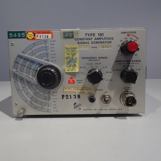
I had a power cord that would work once I removed the power cord condom. Did that, printed out the test section of the manual, pulled off the covers and did a visual inspection:
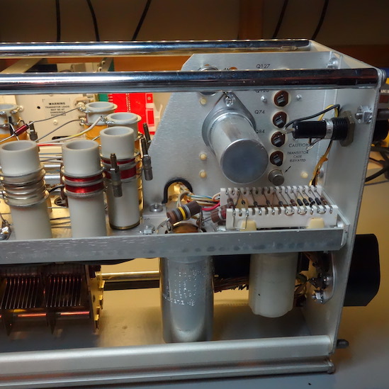
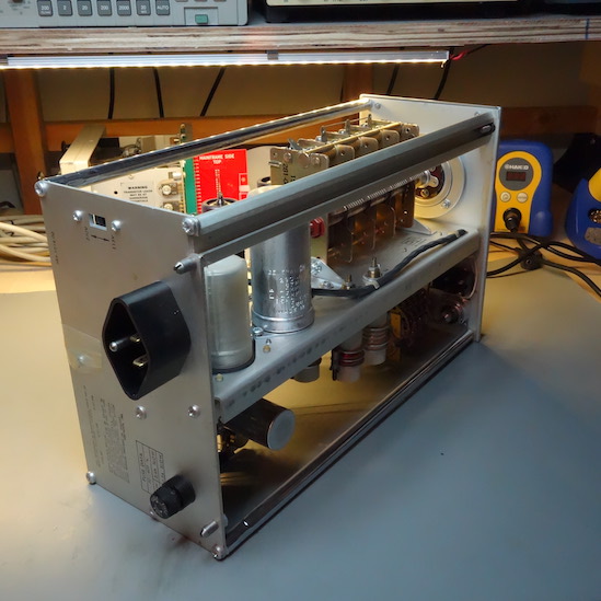
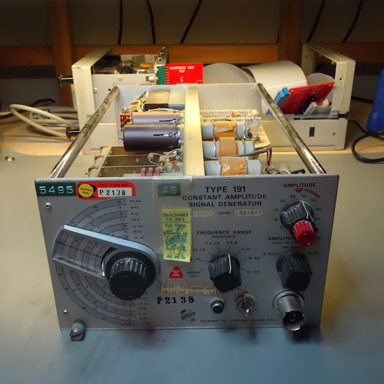
The inside was dusty but otherwise in good shape. No damaged tubes or capacitors. Lookit all that hollow state goodness. I decided to take a chance and power it up. No flashes or bangs and a lovely glow from the neon power light in the front panel. I checked the three DC voltages: -11VDC, +6.2VDC, and

+450VDC. Suddenly I remembered why I decided to go into digital design back in 1978. The 11VDC and 6.2VDC rails were within a volt of spec, +450VDC within 2.5.
Pretty damn good, so I set it up for a middle of the dial frequency, set the output to 5 - 50mV and hooked up an oscilloscope.
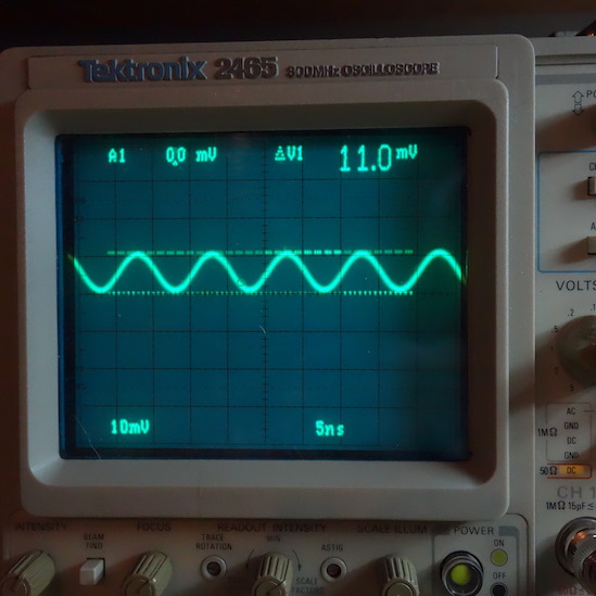
SINE WAVE!

I ran through the voltage output settings and looked at the output through the frequency range. All looked good. Finally, this:
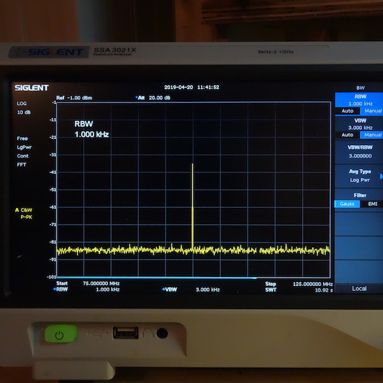
That's the output at 100MHz. Not too shabby for a piece of gear built around 1966 and last calibrated in 1984. Not wanting to press my luck, I turned it off and set it aside until I can do a more careful check of it and run through the full test and calibration procedure.
Just for fun, here's the schematic:
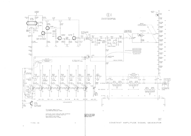
Which can be found here:
http://w140.com/tekwiki/wiki/191#/media/File:191.png