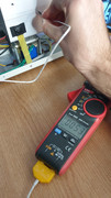
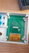
Update: Luckily for me it was quite a simple fix (solder bridge across two terminals of the encoder). Photos speek from themselves. Wish this post will help other buyers in case they have the same issue.
I have also took some pics with an IR camera to see how the unit performs at full load. Maximum temp I could measure was 90 degrees Celsius on the rear top Mosfet. It makes sens why the rear ones are hotter then the first one. (as the air goes from intake to exhaust it gets warmer, so the first mosfet sees a lower temperature, it increases the heat of the air and this repeats until the air is finally exhausted.)
I've placed black electrical tape to insulate the screws from the metal painted case as the heatsinks are tied to the positive input of the load, so a short circuit can happen if you bend the case.
Rerouting the transformer cable it's a good ideea too, they have placed it against the radiator and the metal painted case which is not smart. The cable is long enough to get it in between the two thick blue and red cables and back on top of the pcb connector. Avoiding any melting issues.
A must to do thing would be to take out all 6 Mosfets and replace the thermal compound as it is poor quality and in very low amounts.
What I would also do is to replace the fan with a much higher RPM one (this should be done if you will leave the unit at 400W for hours)
A strange thing that caught my attention was that the bottom mosfets are at least 15 degrees cooler than the top ones. This can also be seen (IR photos) by the electrical tape at the exhaust. (notice the change in color and the 2 different temperatures in the pictures)
Encoder solder issue
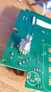
Fixed
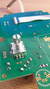
Main pcb
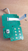
Display Ribbon Cable
Electric tape isolation IR camera sensing
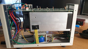
Electric tape isolation IR camera sensing 2
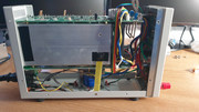
Intake temperature
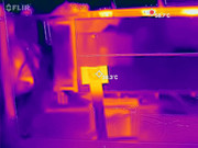
Intake temperature2
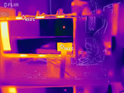
Exhaust temperature
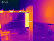
The other side
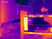
Bottom radiator cooler than the top one
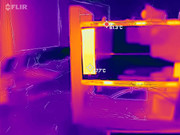
Mosfets at 400W
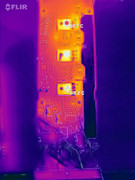
Iron core transformer gets pretty warm, around 40 Celsius
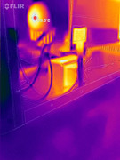
Temperature comparison for the IR camera
