Thrust Bearing Service:

Once you've cleaned the motor, the next step is to service the thrust bearing. If your set screw/thrust bearing is chowdered up from being run dry, you'll need to find a way to get a smooth flat or domed surface for the motor shaft to ride against.
This is offered as an alternate repair method to that in the
article on antiqueradios.com I linked to earlier; I don't know many people who would want to take on building a jig and hand-lapping a thrust bearing surface that way.

The ball needs to be close to the exact size of the hole to prevent chattering; this will still leave 3-4 turns of thread for the set screw behind the ball. If the hole in your motor isn't tight enough to install the set screw on top of a ~3mm ball, you can omit the set screw altogether and fill the hole with epoxy, or you may want to touch up the thrust surface on the set screw instead.
If your set screw/thrust bearing is in good condition, ignore this step and move on to oiling/reassembly.
Another tactic for repairing a chowdered surface is to chuck the set screw up in a drill (use moderate force or you'll damage the threads) and dress the end against the flat of a fine stone or cut-off wheel on a Dremel with the drill running at the same time as seen here. This is a poor man's "precision ground surface".

I use this tactic quite often to repair the ends of "special screws" that have been started crooked and damaged the threads on the end. A little chamfer once the bad threads are ground away and that screw is saved.


This is what this screw looks like right after being ground on the flat of the cut-off wheel; I wouldn't be afraid to use this as-is, quite honestly. Took a couple minutes including setting up drill and Dremel. If followed by dragging across 600-800 grit emery cloth with the drill running, it is surprisingly quick and effective.
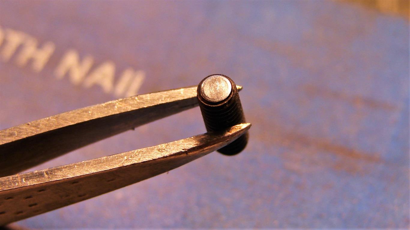
This is what it looks like after running it in the drill with a few quick passes on one of my wife's discarded fingernail buffing blocks. These are NOT emery boards (which my wife steals from me all the time... grrr...

) but final polishing abrasives on a dense foam brick. As you can see here, moderate pressure when chucking up in the drill resulted in no damage to the threads.
It actually took me longer to get three decent pics than it did to refinish the end of this m3 set screw from my parts bin.  Again; if your set screw/thrust bearing is in good condition, ignore these steps and move on to oiling/reassembly.
OILING AND REASSEMBLY:
My preferred lubricant for small motors is full synthetic 0W-30 or 5W-30 motor oil recovered by allowing "empty" oil bottles from an oil change in my car to drain into an old pill bottle like this one overnight.
I use a ~ 2mm wide blade-tip screwdriver as a precision applicator; dip it in the bottle then quickly apply 2-3 drops right on the shaft and let it sit for several minutes in an upright position before doing the same on the opposite end. Repeat for both ends, and repeat again if it appears to just suck the oil in. There is felt batting around the bushings; you are trying to re-saturate it with fresh oil.
This is a brushless motor; the worst that can happen is some oil mess. Of course, use some common sense... a big puddle of oil in your 24xx later could become a big hassle.

Let the motor sit overnight after oiling if you can; this will give the oil plenty of time to soak into the batting, and you'll be reasonably sure it's not gonna drip after you reinstall it.

Reinstall the set screw/thrust bearing. Just turn it in a few turns; don't tighten it.
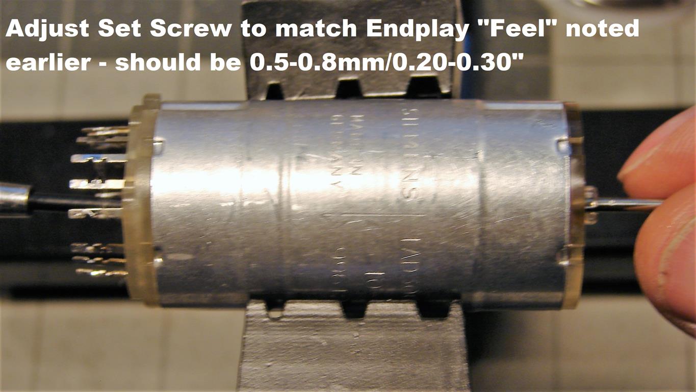 Sorry for the fuzzy pic; it was the best one of several and the motor's all back together now.
Adjust endplay so it feels the same as when you first disassembled the motor. Your fingers are a pretty good judge of what's reasonable endplay. If you feel a need to mic it out, or if your set screw was chowdered up or missing obviously this will be way off; look for 0.5-0.8mm.

Use your sealant of choice to close up the hole and lock the set-screw in place. I prefer silicone RTV sealant as it is eazy to remove if needed.
DON'T FORGET THE PLASTIC SPACER when you reassemble the motor to the driver PCB.

TESTING:
A healthy motor will start at around 8V with a 30mA draw; set your power supply with current limited accordingly for initial test. The shaft is hard as hell and mirror-finished; a mark with a Sharpie will make it a lot easier to see when it starts turning. Let it run a few minutes, checking resistors and driver IC to be sure they get no more than warm.

Here we're going to put the fan on temporarily for performance tests. Just press it onto the collet cone; it will hold. No sense to risk breaking it by tightening the nut.

Here we're running at 12V; it's drawing approx 60mA. Fan is running just above idle. Note location of thermistor and pinout of 0.100" power header.
Dont forget to test/replace that electrolytic cap seen on the upper right corner by the motor. It is prehistoric too. 
Idling at 8V; drawing ~40mA.

Idling at 12V; drawing ~55mA

And here's the last step; testing the thermal speed control. Place your soldering iron CLOSE to the thermistor, but don't make contact. The fan motor should start to ramp up speed in a few seconds. You'll need to up the current limit on your power supply if you haven't already.
Do several cycles of "apply heat, fan speeds up / remove heat, fan slows down" and observe the motor; it should still be pretty much dead silent at these low voltages. IIRC, it runs on 18-20V in situ. Remember to keep checking resistors and driver IC for overheating while testing.
If it runs cool and quiet, time to put it back in... unless you haven't let it sit overnight since oiling it.
You REALLY should take the time, just to be sure of no oily puddles.
Cheers,
mnem
The higher the faster, of course.


