The subject of this several part post will be a road map for re-capping the PSU Regulator/Inverter boards in the 2465, 2465A, and 2465B. It will not cover known issues with the A5 board which went under considerable change through out the 24XX series. I think most of what will be discussed here will also apply to the 2445 but I'm not totally sure. If someone knows that answer go ahead and chime in.
The candidate: The top 2465. The bottom 2465 DMS had it's PSU re-capped 2 years ago by me.
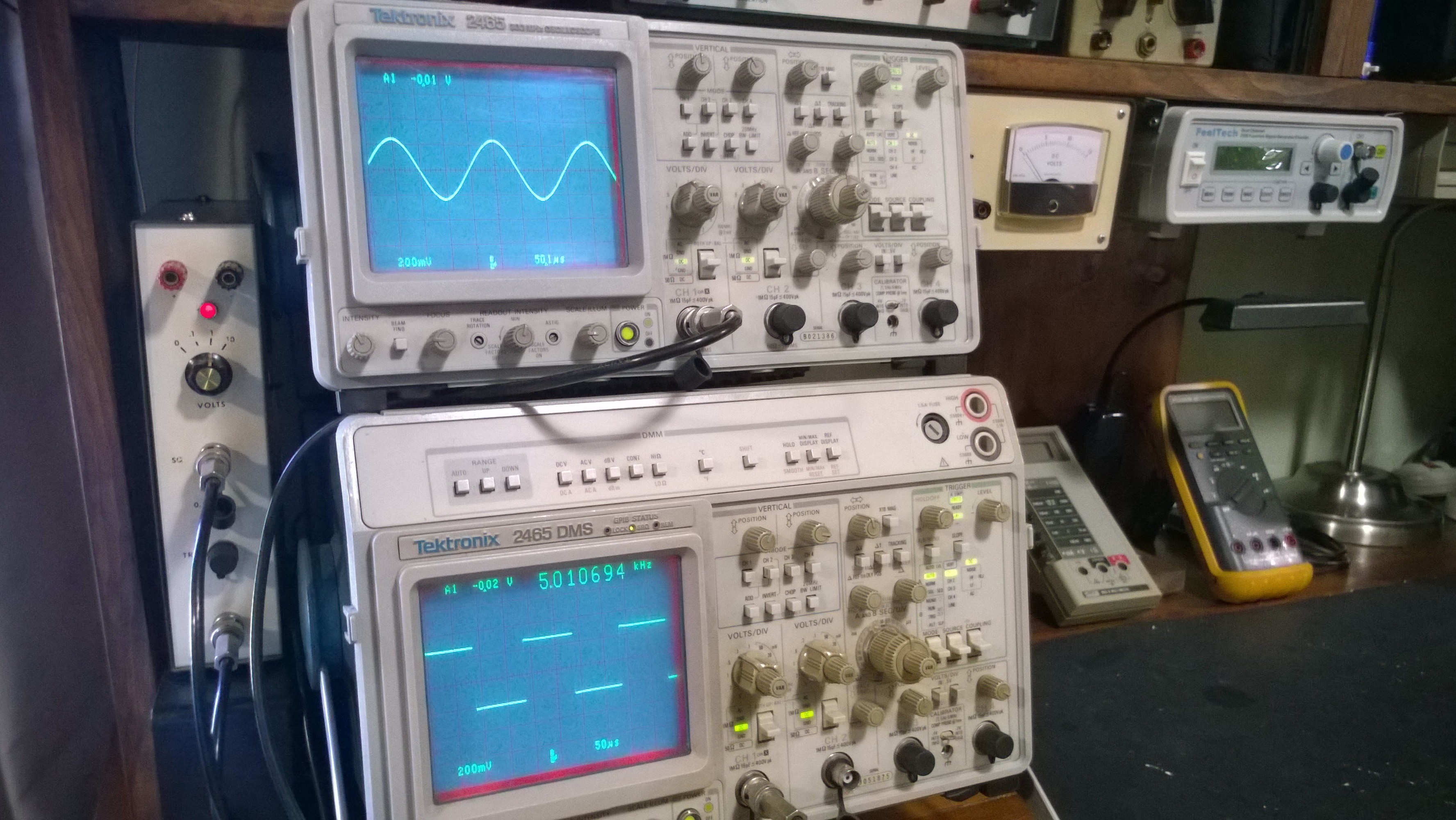
What I know about this 2465: I purchased it 2 months ago. Appears to have a build date of 1983. It was owned by IBM. I suspect it has low hours judging by it's condition which is very good. (The 2465 does not have EXER05 which logs the hours so I can't be absolutely sure). No errors on power up and all critical parameters appear to be in spec. I had it apart about a month ago and measured the supply voltages at J119 and they were all in spec. The supply caps are all original hence the re-cap. But no leakers were observed.
Tools required: All the fasteners in the 24XX are torx. So you will need a suitable driver. Also refer to post #1069 where I attached the cap replacement chart used. All the caps were purchased from Mouser.
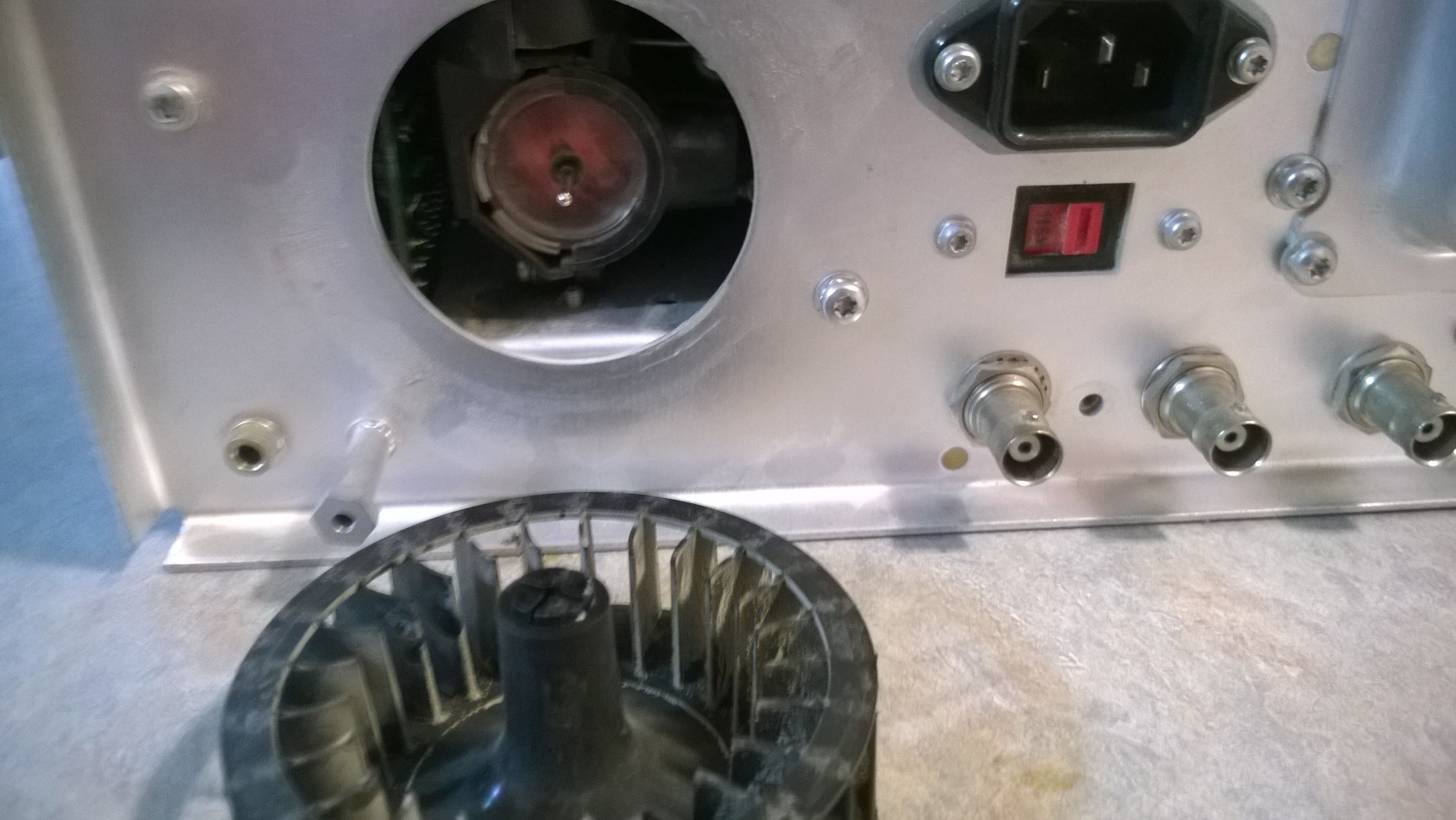
Upon removal of the rear cover if you have a 2465 you will encounter this cage fan. The 2465A and B use a conventional computer type fan which requires no additional attention. This cage fan is notorious for becoming very noisy and rattling. The one in this 2465 is whisper quiet, which gives me additional evidence that this scope has low hours. The cage fan in my 2465 DMS rattles like hell for about a half hour and then settles down to quiet. I do have a replacement computer fan built up and ready to be installed if required but will require modification to the rear cover. The cage fan is driven by a Siemens motor which is unobtanium as a replacement and ridiculously complex to rebuild as shown by this link:
http://antiqueradios.com/forums/viewtopic.php?f=8&t=235478
Remove the center nut on the fan. Spray some Deoxit into the center hub to act as a lubricant. Now the fun begins. VERY CAREFULLY start to pry the fan off the shaft. If you are lucky the fan and center collet will come off in one piece. The other alternative is that the fan will come off and the center collet will remain on the shaft. That's also OK. But what most likely will happen is the collet will snap in half with part on the shaft and part inside the fan. But don't worry, it can be epoxied back together. This happen to me when I pulled it apart a month ago but didn't happen this time. And you are not alone here, it happens to just about all of them.

The fan successfully removed from the motor shaft.
And now to the top cover. This 2465 has no options so just remove all the fasteners and pull it off. But if you have any options such as GPIB, Counter/Trigger, Probe Power, etc things are a little more complex. There will be a buffer board attached to the underside of the cover and additional wiring interconnects, including to the PSU. Note where everything goes and take additional pictures if necessary. If you have a 24XX with the DMM option you have to totally remove that board before you can even access the top cover. And wiring interconnects running all over. And it's a nightmare to put put back together. The 2465 DMS is that nightmare.
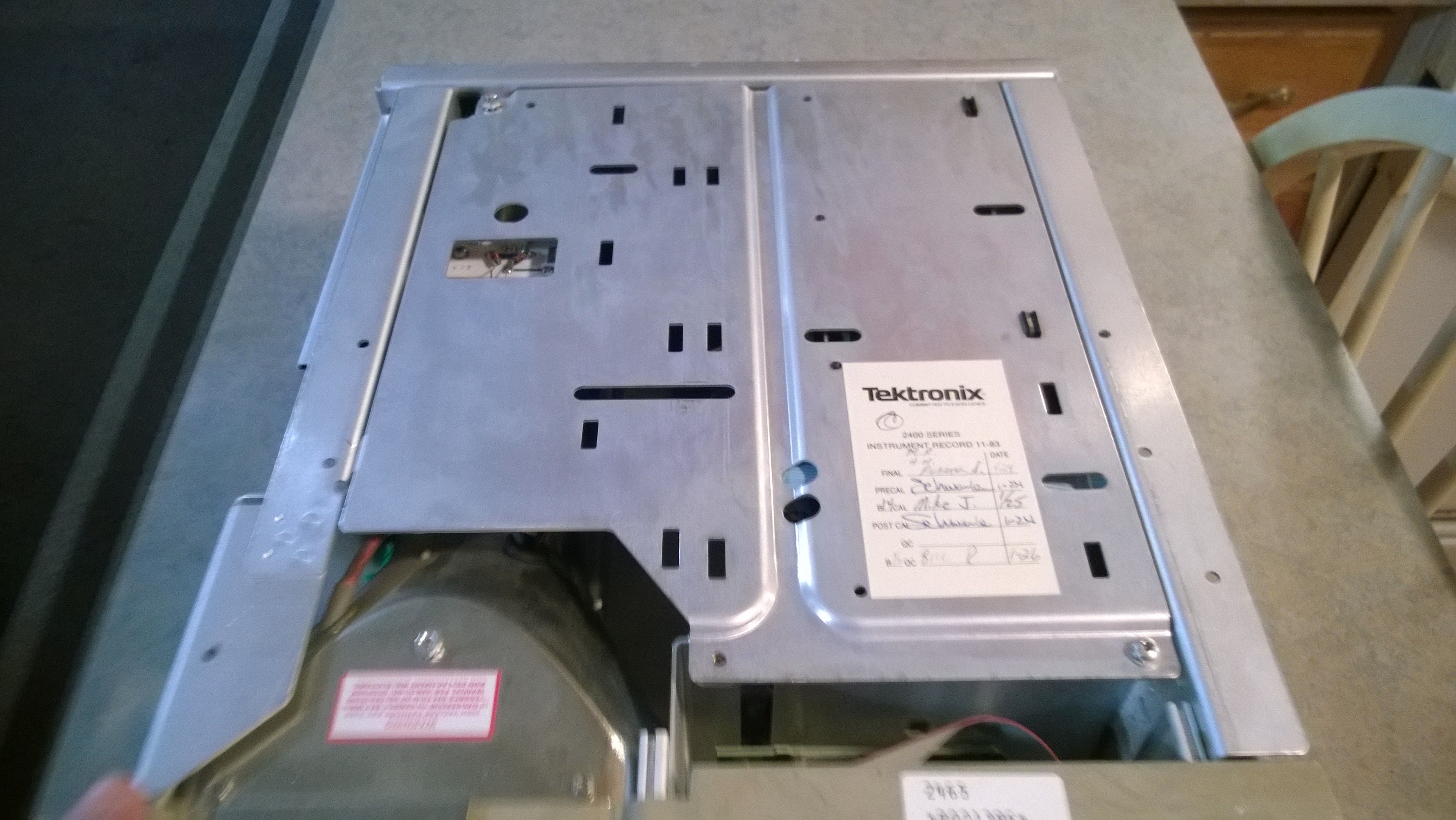
Once the cover is removed the supply is now accessible. Part 2 will remove it and get it ready for re-cap.


