Pulling this back up to the surface as I could really use some help from a fellow DS/MSO4000 owner.
I spoke to Rigol who said that my symptoms usually is the result of bad powersupply so I ordered a replacement from them which arrived today. I exchanged the old one and powered up the scope. This time it didn't say "click" it said "pop" - I could both see and smell the magic smoke and I could see roughly where it came from.

After inspection of the area I could not find any visible damage so I removed the main PCB in order to inspect the other side and the damage was pretty obvious. A dead short across one of the 47uF/35V tantalum capacitors for the "upper most" switch mode supply.
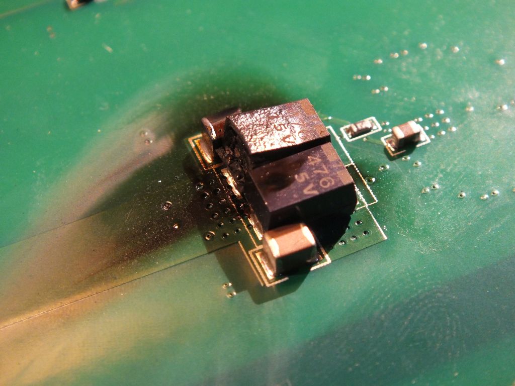
Since the power supply didn't shut down on overcurrent (at least not untill I pulled the plug (I was prepared)) it also took out the MOSFET (FDS4435A) that sits between the power input connector and the rest of the system so that's now shorted as well but I don't think it matter much for further trouble shooting, it will be replaced in the end though. I removed the damaged capacitor (actually all four), cleaned the PCB (it was pretty badly scorched under the shorted cap, I hope there wasn't any internal traces at that spot) and measured from V+ to GND, no more short so that's good.
The good thing with getting the new powersupply is that it had text silkscreened around the output connector so now I know that the there is only one output voltage (around 20V). So I tried powering the board up using a lab power supply set to 20V with a 3A current limit but the board just makes the characteristic hissing noise and lab supply goes into CC. I'm not sure I want to try raising the current limit further at this point.
So, finally, here's what I'd really appreciate some help with:
Is anyone willing to open up their DS4000 and do some basic measurements? There's no need to remove the main PCB just take the scope apart and remove the back metal shield case.

What I'd like to know is the resistance between GND and points (A), (B), (C) and (D) and - if possible - also the voltages at these respective points when the scope's running would be awsome.
EDIT: I've traced out a couple of the feedback networks and as far as I can see output (A) should be 5V and output (B) should be 3.3V.


