I happened across another Hitachi V1065 recently so thought I'd take a few pics this time as I checked it out.
Hitachi made several 'scopes and the V1065 is one of a series of very similar instruments made in the mid-late 80's. It's a 100MHz bandwidth analogue 'scope with cursor readout. They're actually very nice 'scopes to use although there is a bit of "one knob does everything" going off with some of the settings. The tubes are very nice and have an utterly pin-sharp trace. They are also a nice 'scope should you need to do any DIY fault finding as they are almost completely standard parts (except the custom CPU).
Manual including schematics at
http://www.wild-pc.co.uk/docs/Hitachi-V-1585-65-60-V-695-OM-Schematics-English.pdfThere was a thread recently on what constitutes a teardown - this is more a take-apart than teardown but I still find it useful to see how something goes together. As it happens there was no great problem with the 'scope - the small selector switch used to control the function of the "variables" knob was sticky and didn't return cleanly to the centre position - getting the front panel PCB out to get at it to clean/lubricate it needs pretty much the whole 'scope taking apart.
In fact this is really a tear-up as I'd got the whole thing apart before I thought of taking any photos - so they were done in reverse order as I put it back together.
Overall view (click on pictures for high res version).
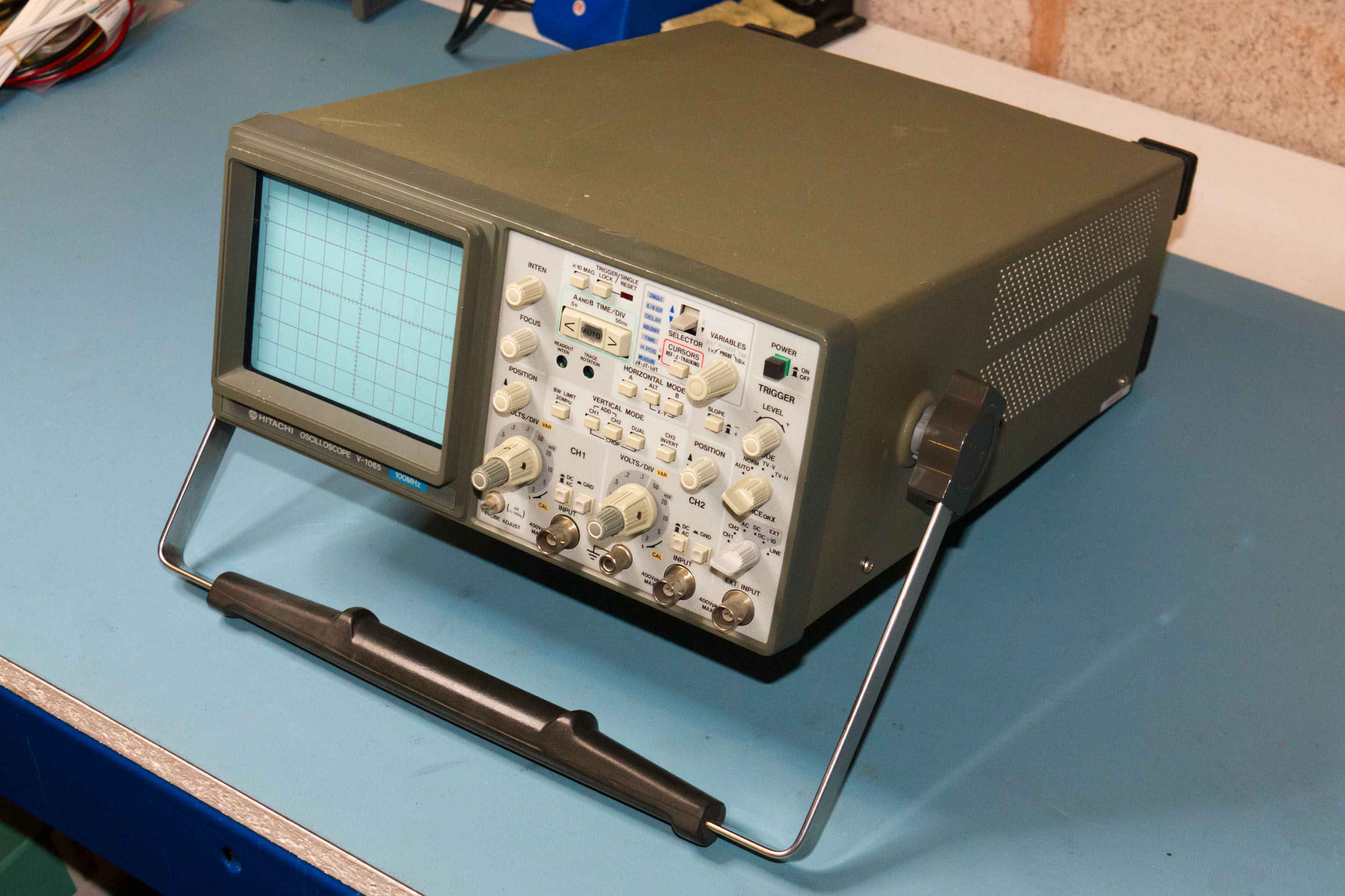
Whilst obviously not as small or lightweight as a modern DSO these are very compact. Military green seems to be the only colour though

Taking a peek inside
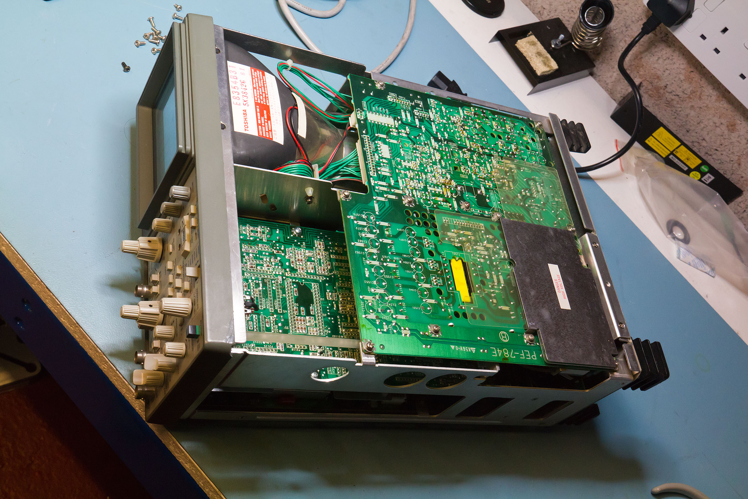
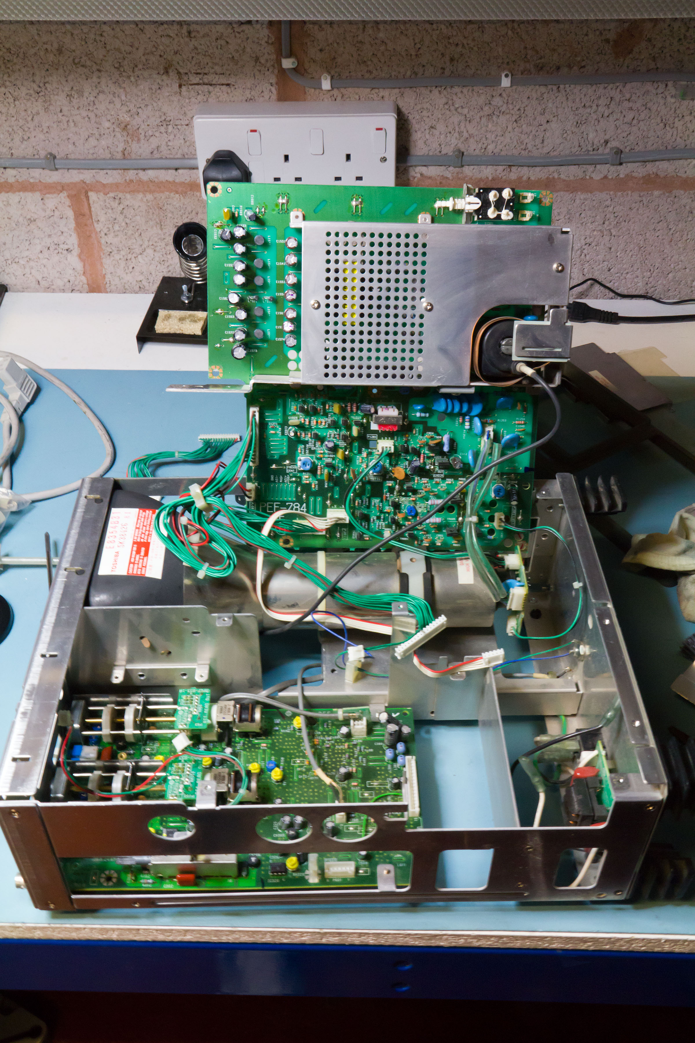
The top board is the PSU including all the high voltage sections - there is some protection for these but I don't think I'd want to accidentally put my hand on here with the thing powered up. The final X amp and Z-mod circuits are here as well.
The PSU board has a hinge mechanism which allows it to swing up towards the front of the 'scope. I'm not sure if the intent was that he instrument could be run powered up like that as it's hard to get to the CPU/X board to fault find but if so then it's a bit of a fail. The two mains input leads and another inter-board connect are way too short to allow the PSU board to swing up.
I find it's easier to swing the PSU board out to the side. In fact the 'scope can be powered up like that if the mains input to the board is extended (and one is very careful with the position of the board - lying the board flat on the bench with the 'scope on its side works best).
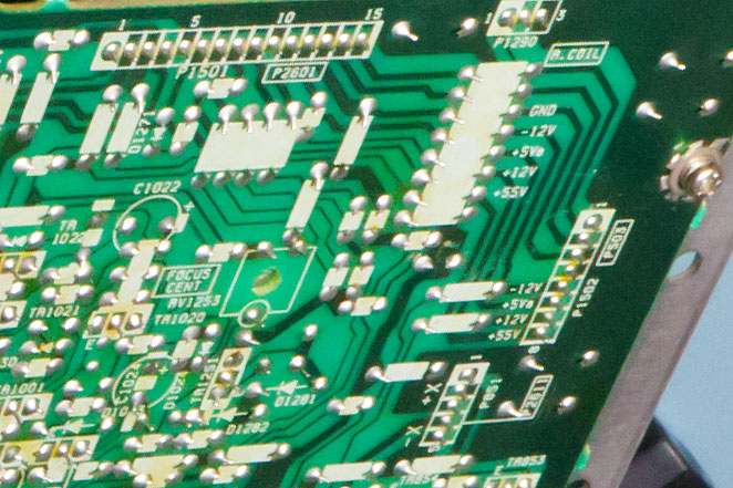
The back of the PSU board has nicely labelled points to check the supply voltages.
Swinging the PSU out of the way shows the next board down which is the CPU/horizontal board.
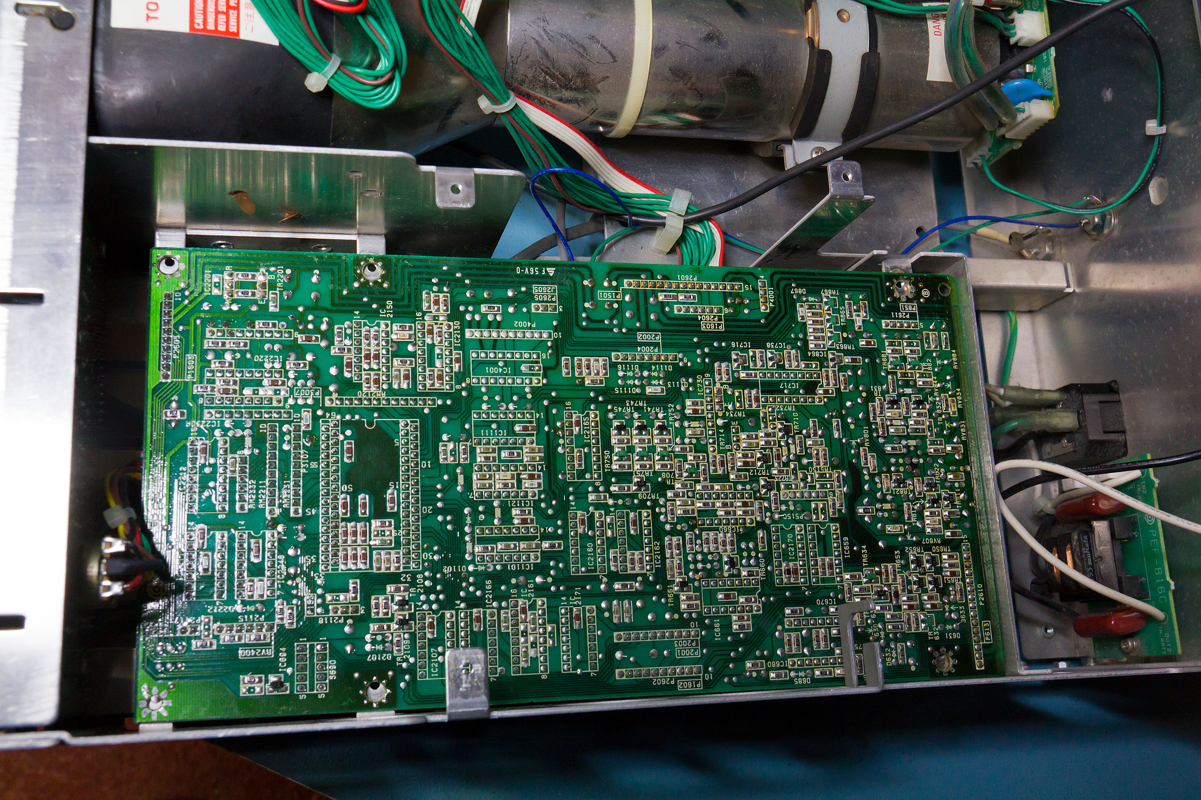
Construction is a mix of SMT and through hole. Most (but not all) of the passives are SMT with the ICs (mostly 74LSTTL on the CPU board) in DIP packages.
Flipping the whole thing over shows the solder side of the vertical board and the delay line - which looks huge compared with the ones in the Tek 2200 series 'scopes.
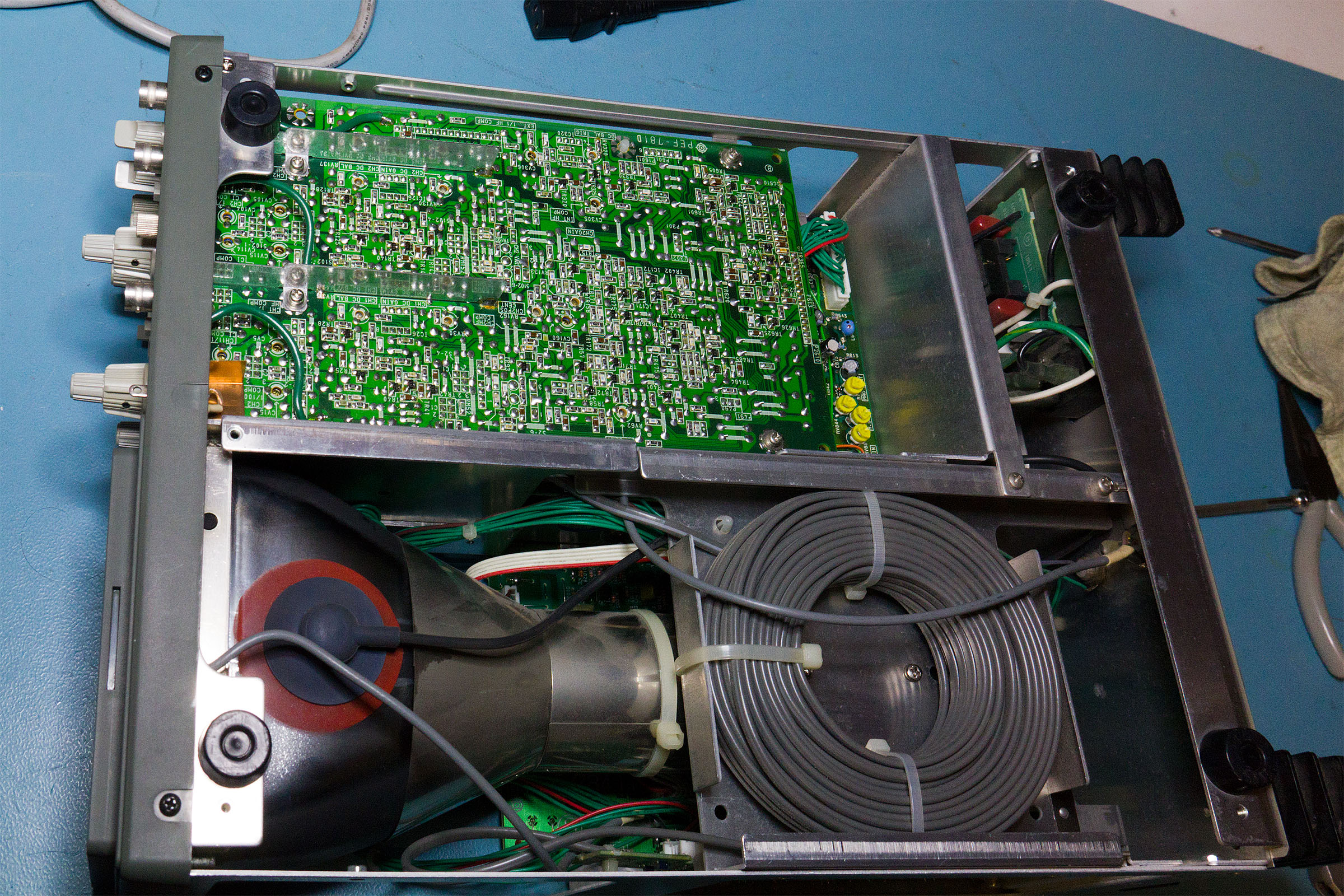
You can just see the yellow trimpots for calibration on the horizontal board - all in the same area of the board. In fact you can get at these by taking off just the bottom of the case.
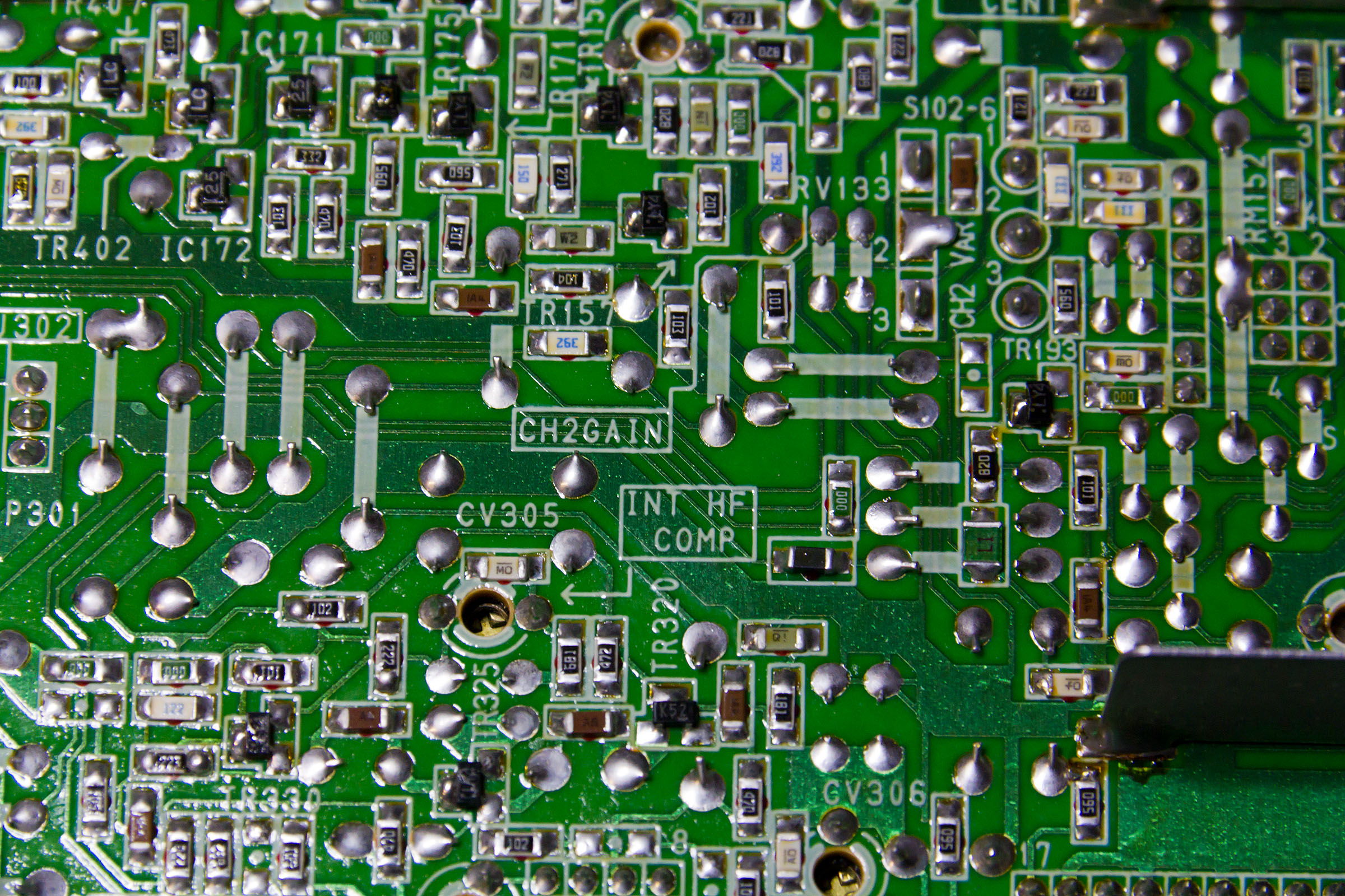
The vertical calibration points are all on the component side of the board but with holes through to allow access. They are all nicely marked on the solder mask as well.
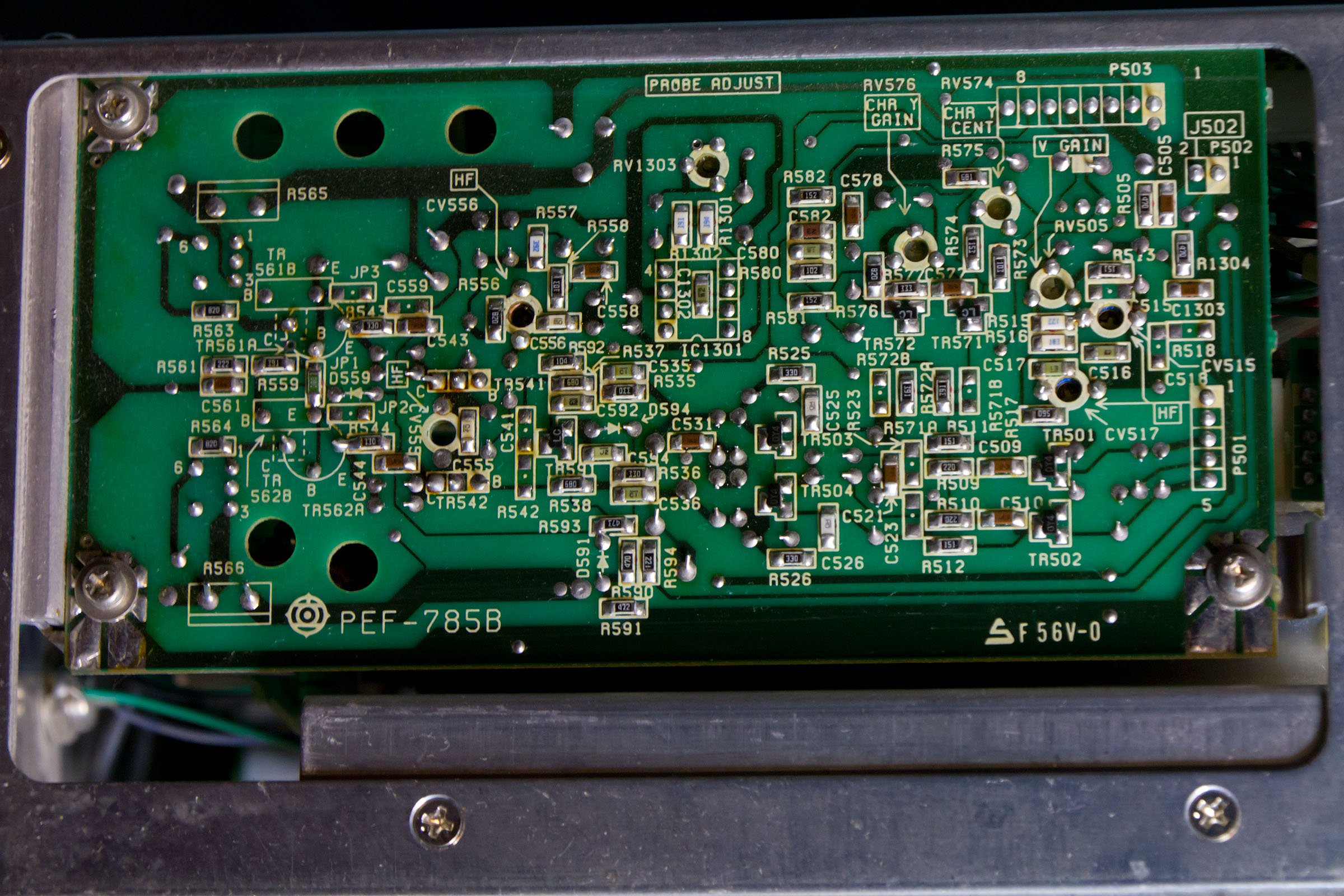
Round the side is the final Y amp. You can only really see the solder side of this board as it's close to the end of the CRT. Again the functions for all of the variable caps and resistors is marked on the silk screen.
Trying to get the CPU board out is made harder by the fact that not all of the interconnects are long enough - it gets just far enough out to start to disconnect everything
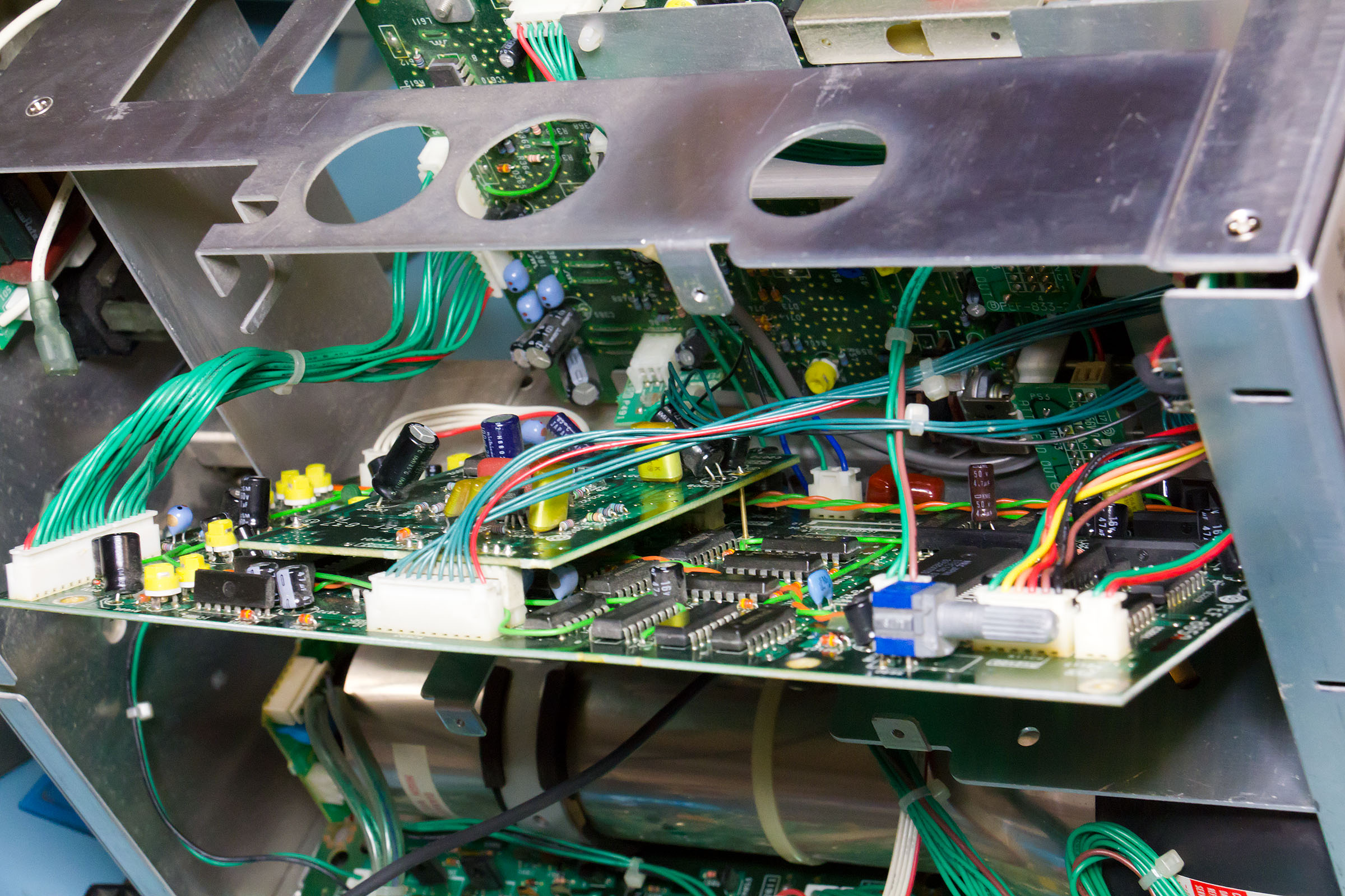
Once a few are unhooked it's possible to swing the board up. Almost all of the header plugs are different sizes so it's fairly easy to make sure everything is going to the right place on reassembly.
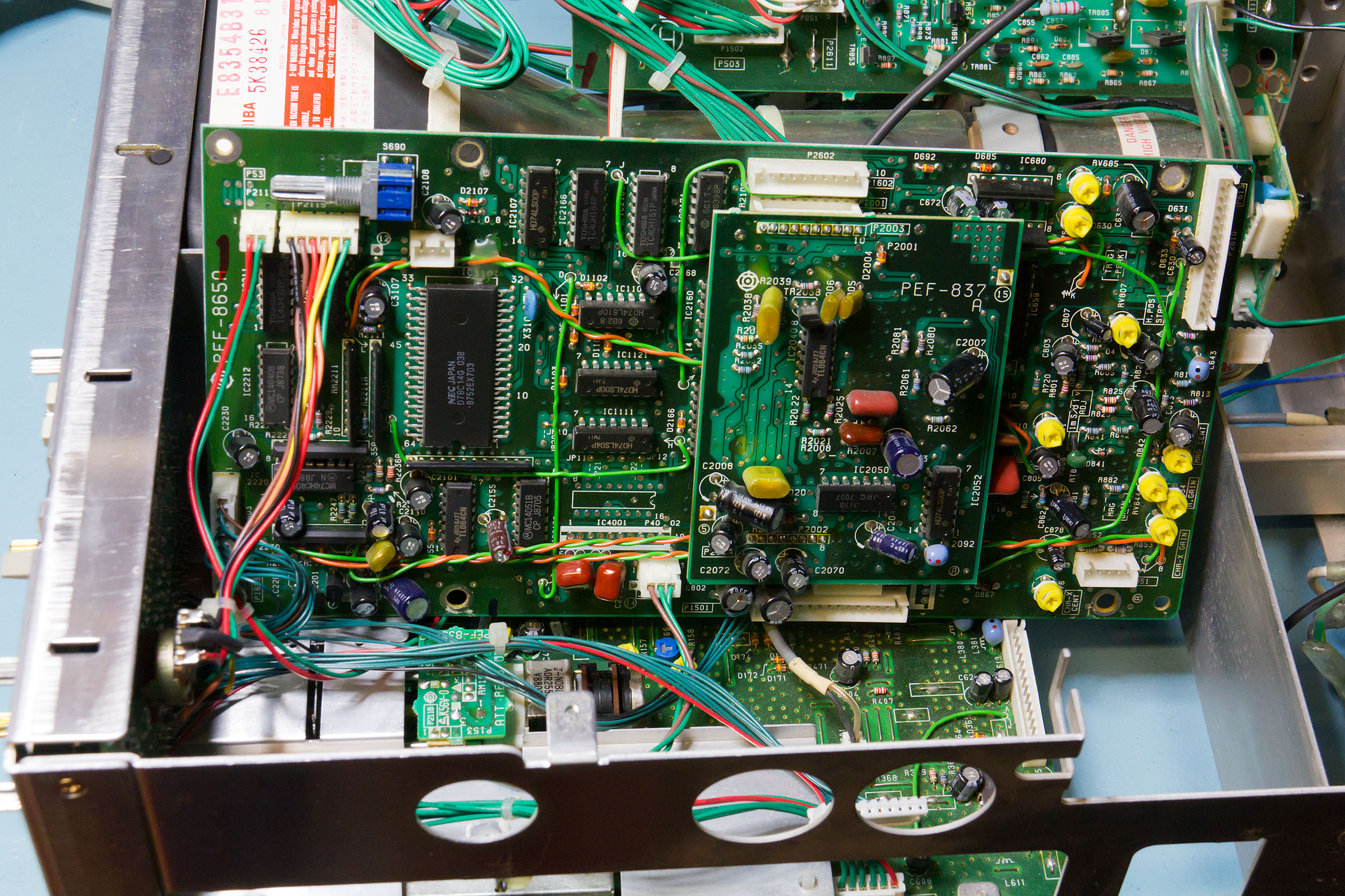
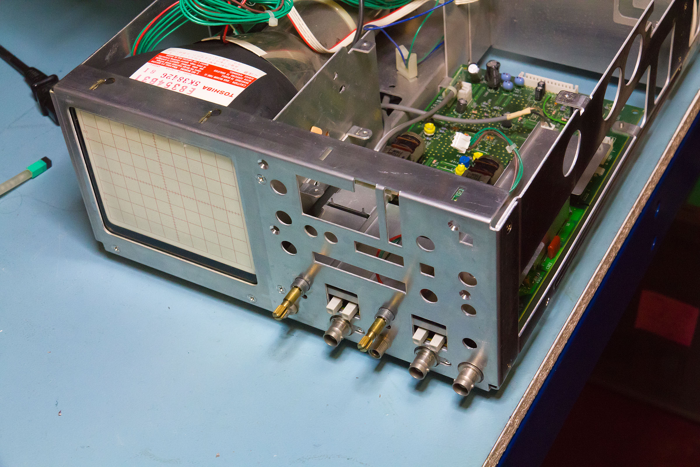
Finally we have the boards out and the chassis is looking a bit bare but we can get at the gummed up switch. Strictly speaking I didn't need to take the plate off which forms the visible front panel but it badly needed a clean.
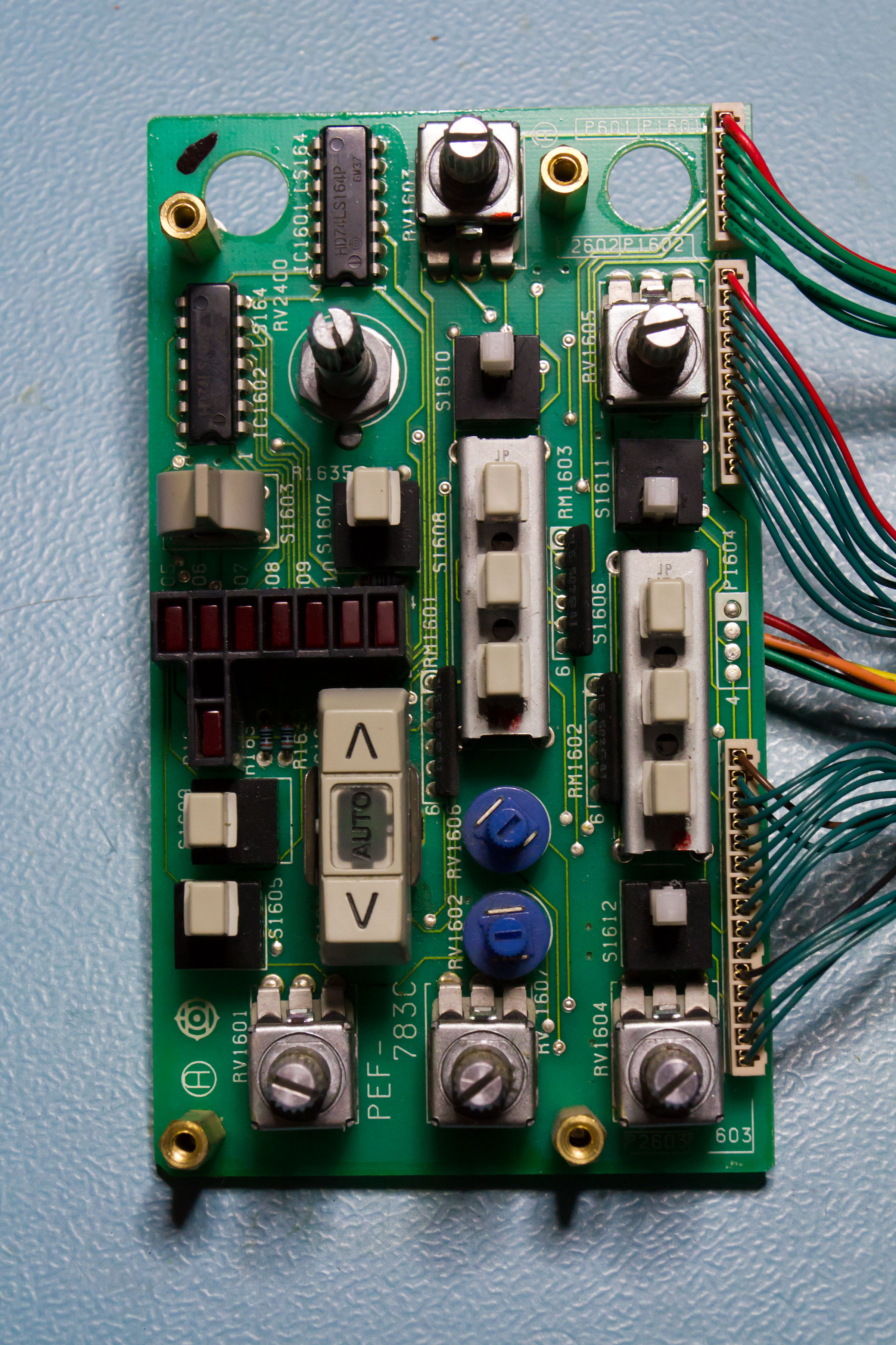
The offending item is the toggle switch just above the array of LEDs - underneath the paddle there's a fairly normal centre biased toggle. A quick squirt of switch cleaner and a bit of light lubrication and it's as good as new.
The CPU is an NEC D78C14G micro-controller. Odd 64 pin "quad" DIP package which was briefly used in the late 80's before (thankfully) disappearing. It appears to be a bit Z80ish but doesn't have compatible machine code. Date codes on the ICs suggest a mid 1988 build date for the 'scope as a whole.
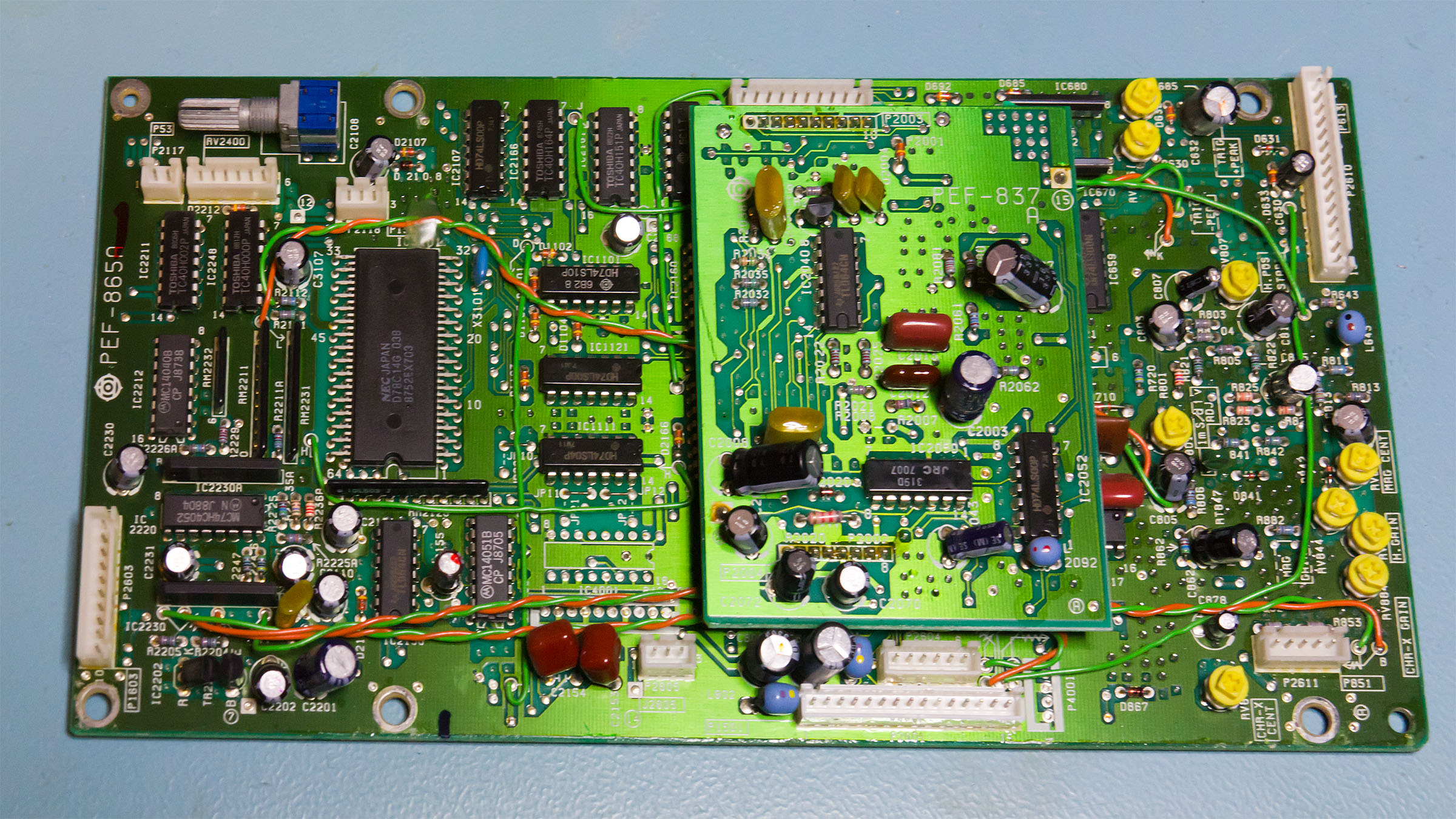
Datasheet for the CPU at
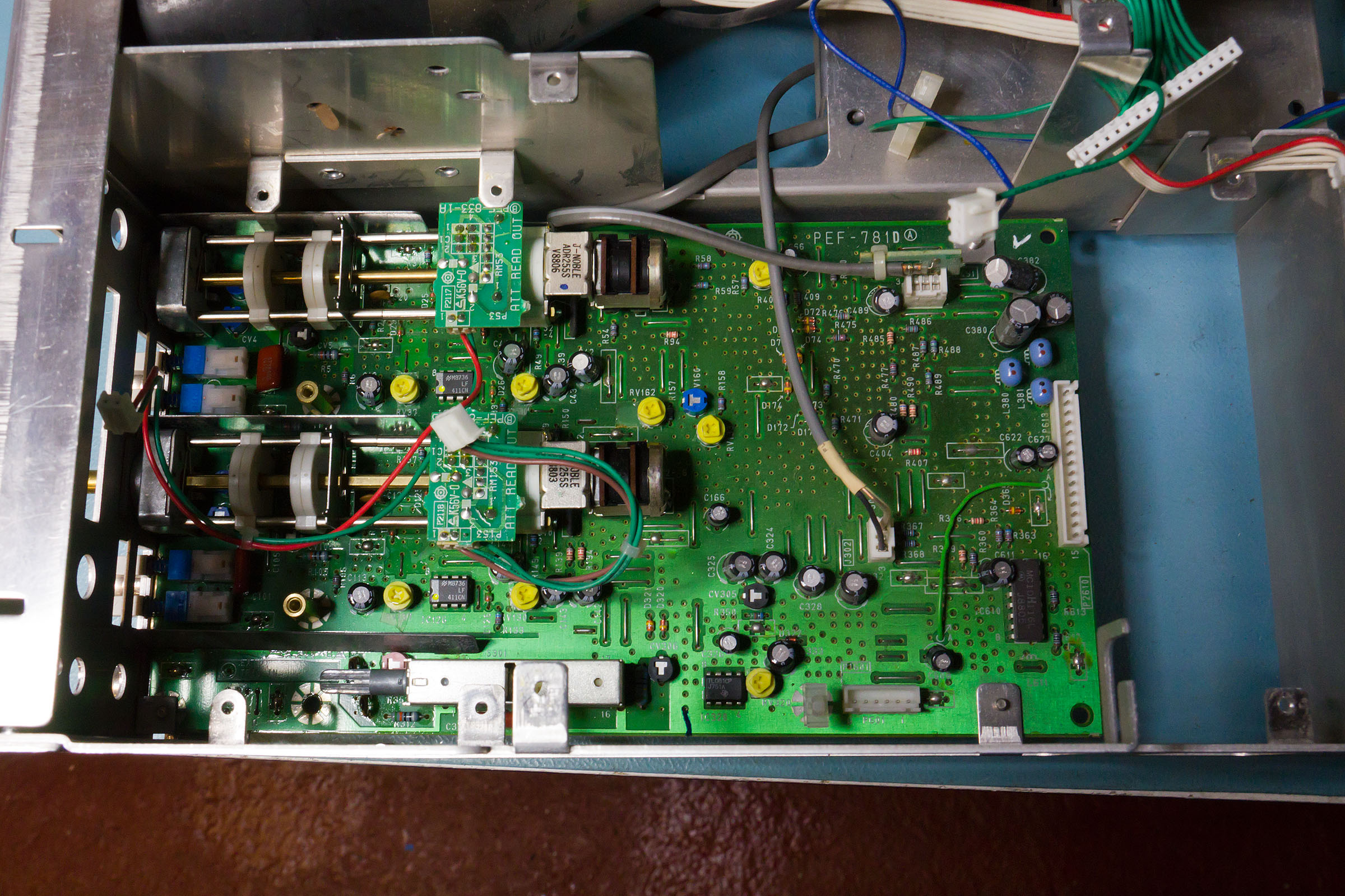
http://www.wild-pc.co.uk/idocs/NEC_D78C14G.pdfLooking down at the top of the Y board we can see the readout boards which tell the CPU which attenuation has been set, otherwise there isn't actually much to see on this board.
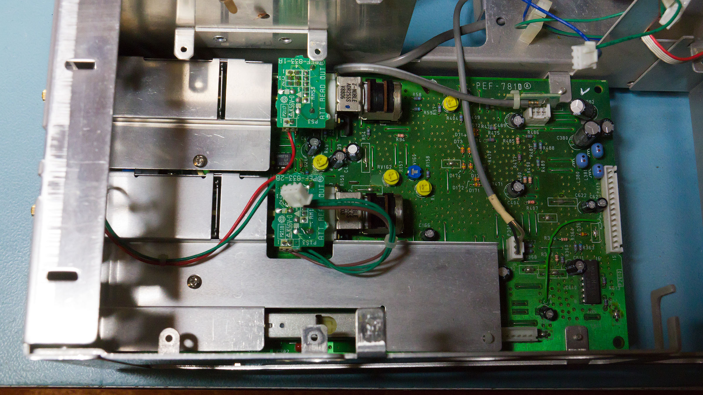
Even with the screening removed the board is fairly boring.
Finally a shot showing how I swung the PSU board out of the way. The high voltage side is screened off (it almost touches the CPU board when everything is installed.
The screening mostly hides the two transformers.
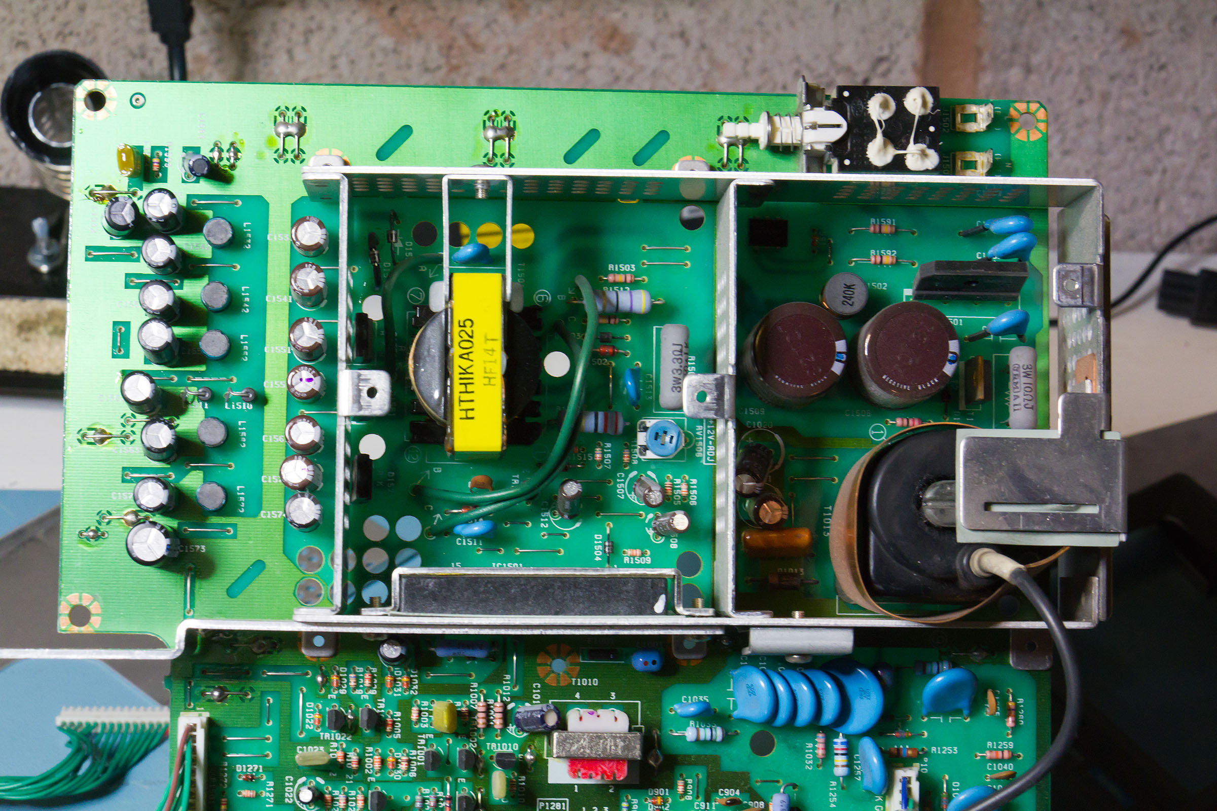
The CRT anode potential is 15kV. Slightly unusually this is generated straight from the HV transformer - there is no multiplier (at least if the schematic is to be believed).
Finally back together and running
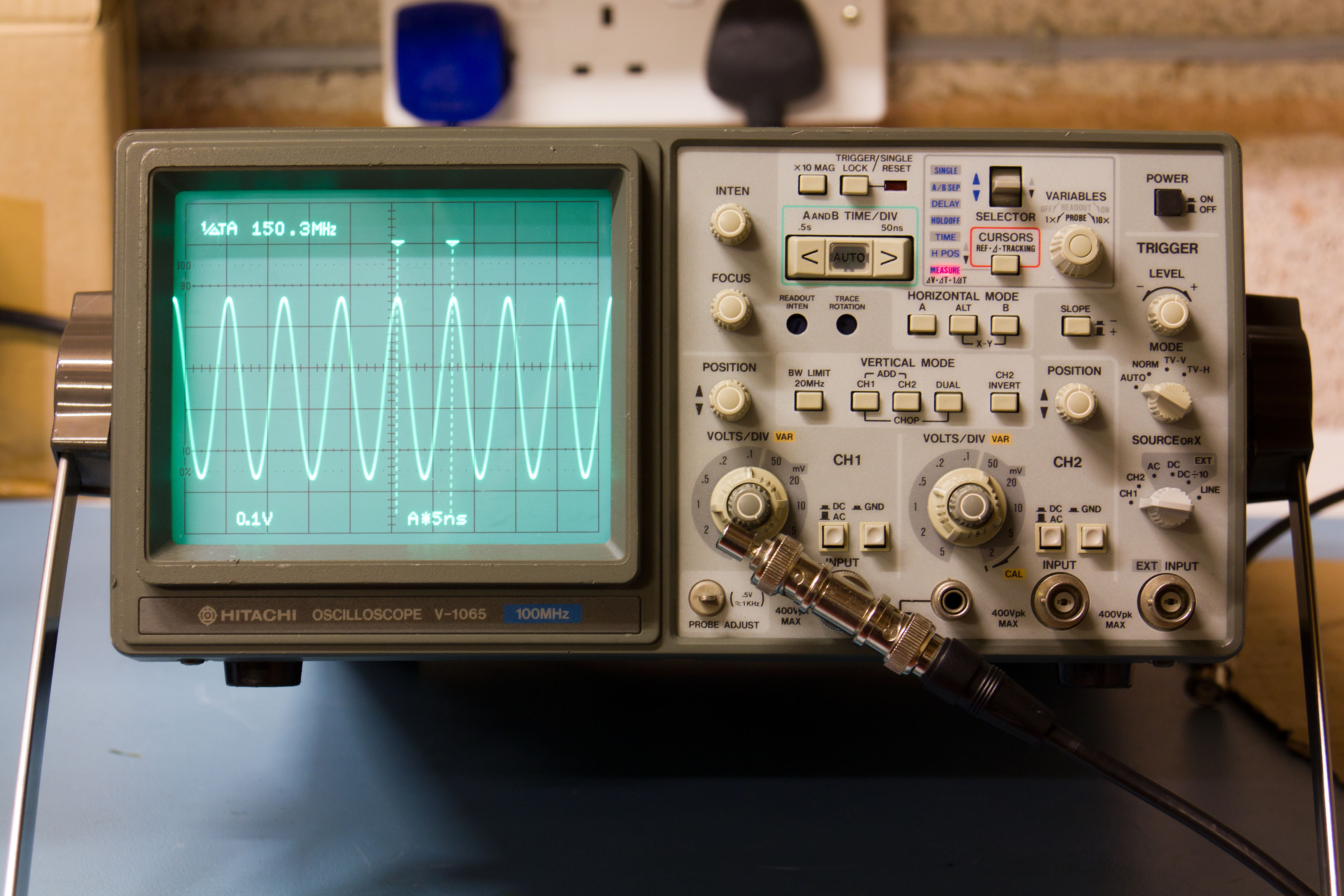
For a notionally 100MHz 'scope it does rather well - though the frequency response is a bit odd. It's about 2-2.5dB down at 100MHz but then drops slowly to not quite 3dB down at 124MHz before increasing a bit for a few MHz, then falling again and finally hitting -3dB about 150MHz, then tailing off as expected. Max stable trigger is around 150MHZ (although it's a bit tricky to get a clear display at this frequency).
Hope you enjoyed the teardown folks
