There is a test you can do: use a direct connection between the calibrator output and the input (or use a function generator with a square wave output). If the effect is gone then the problem is likely that the input capacitance of the scope isn't constant and throwing off the adjustment for the 1:10 probe. If the effect persists then it is likely a factory calibration error or out of spec component.
Signal from generator.
SDS1203X-E analog front end have 3 different vertical bands.
Test signals to scope input. Gen out - Suhner RG223/U 1m - Tek 011-0049 - SDS1kX-E input.
Attached images:
Vertical band 1. 0.4V Sqr Scope vertical 100mV/div, probe multiplier 1x
Vertical band 2. 0,8V Sqr Scope vertical 200mV/div, probe multiplier 1x
Vertical band 3 8.0V Sqr, Scope vertical 200mV/div, probe multiplier 1x
Of course square is not flat because frequency response from 0Hz to 200MHz is not flat. I do not know any single scope where this frequency response is flat, not even if scope price is same as house.
In this test small change in input capasitive reactance between V bands do not affect so much it can detect. Most part of difference between ideal square wave come from frequency response flatness.
Situation with these probes when probe is set for 10:1 (10x) is bit different.
There can see some LF compensation error.
In this case my opinion is that it is possible that square wave is disturbed due to small change in oscilloscope 1Mohm input (capasitive) reactance change. V bands 2 and 3 have not so much difference between each others but V band 1 change capasitance more. Change is perhaps even some 1pF's and it affect to this probe Low Freq compensation. {
Siglent development team need take this into consideration}
Every V band (I, II and III) have separate pathway what are selected by relays. There is not adjustment for null these capasitive input reactance differences between vertical bands.
I do not want speculate if different probes are less sensitive for this small reactance change.
If want, it can also say that this error do not violate given specifications for frequency response error limits or level error limits, not even close. But cosmetically...., well - it can be better also my nose can be more beautiful. Ideal pure square waves can find only in kids school books.
All what human see in oscilloscope display is sum of errors added to unknown truth. After get real long time wide range experience people can live with errors mixed with unknown and still he can do his jobs.
I have not any even minor difficulties to do my works with Tektronix 2465, HP old digita or some more new digitals and also including this SDS1202X-E. I have not any single equipment what do not tell me wrong things. All frequencies are off, all voltagfes and currents are off, my clock os off. My straight line is not straigth, my micrometer is wrong, my temperatures are wrong. I not know anything what is right. I have brains for live with all these errors and they do not stop or other way fail my work. If my brain or heart go to too big errors, then my works fails.
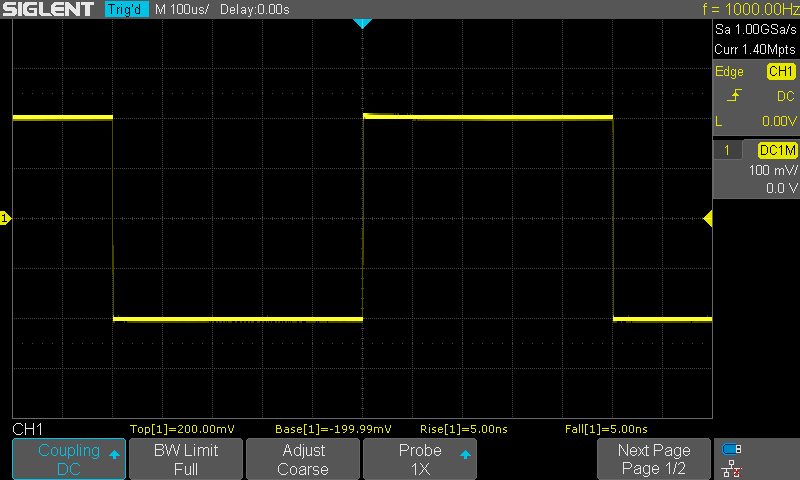
Vertical Band I
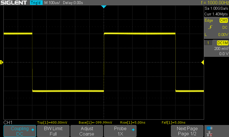
Vertical Band II

Vertical Band III


