-
I have just uploaded the first part of my review of the new Siglent SDS 1202X-E!
I will be doing some more detailed followup videos, so remember to subscribe while you are there
Check it out here: https://youtu.be/64kxGDOg7es
Big thanks to Rob (TauTech) for the loan of the unit. -
My more detailed Part 2 full review is now up on YT as well, check it out below:
https://youtu.be/laK1v2Zas4o -
Needing a nice & clean waveform to do decoding properly?

No, that is not normal for any scope and hence the threshold setting to turn whatever junk into a signal with clean edges. For example: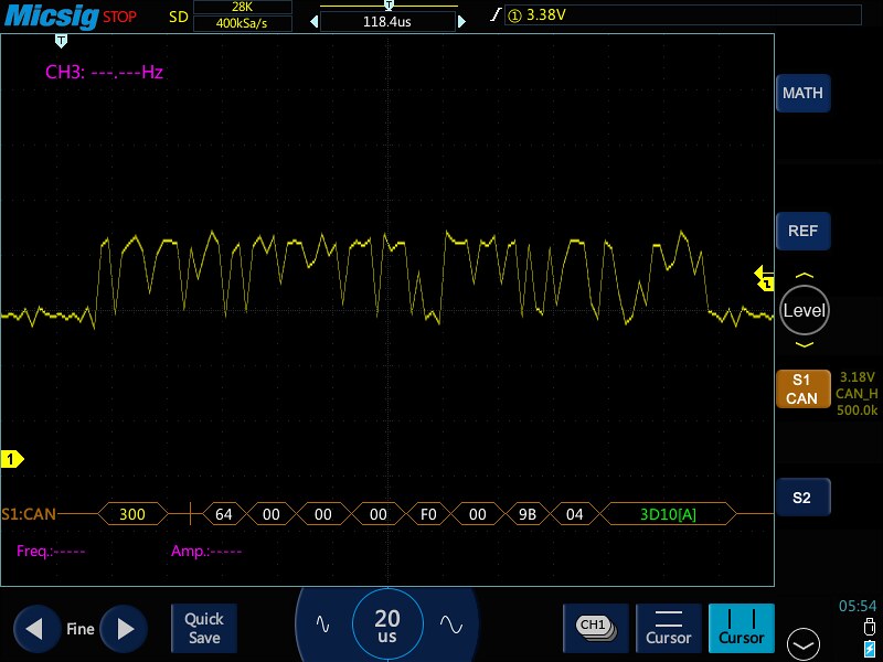
-
$412US?!
Can you tell me, on the measurement menu, for rise time, fall time and pulse width, can you set the reference point? By default the mid reference points are usually 50%, but in my uses, for Fall Time, I set it at 10% and 90% and the mid reference points both at 10% (or 90% depending on the perspective). This is how you measure the values of an ultrasonic pulser. I can see on a flyer that you can measure pulse widths, fall time and rise times, but I don't know if you can set the reference measurement points for those readings.
Dave -
$412US?!
$379
http://siglentamerica.com/pdxx.aspx?id=5109&T=2&tid=1QuoteCan you tell me, on the measurement menu, for rise time, fall time and pulse width, can you set the reference point? By default the mid reference points are usually 50%, but in my uses, for Fall Time, I set it at 10% and 90% and the mid reference points both at 10% (or 90% depending on the perspective). This is how you measure the values of an ultrasonic pulser. I can see on a flyer that you can measure pulse widths, fall time and rise times, but I don't know if you can set the reference measurement points for those readings.
This is normally done by your positioning of the waveform on the display if read from just the graticules, but with the cursors and the OSD measurement the waveform can be anywhere on the display and you have control of the % level you want the cursors and the measured rise/fall times between the cursors.
Hope that helps.
-
""the measured rise/fall times between the cursors.
Hope that helps."
You can manually measure fall times and pulse widths with any scope with cursor. I am asking about automatic measurements. I see from the flyer that you can select Fall Time, Rise Time and Negative Pulse width. This reading would show on-screen. Now under that measurement menu, can you specify reference levels or pick-off points used to calculate those measurements?
On a Tektronix TDS-3032/3054, under the measurement menu is a Reference setting. By Default, the High reference is 90%, the Low Reference is 10% and both Mid References is 50%. Since I measure a negative going pulse that kind of, remotely, sorta, looks like an upside down bell curve, I set both mid reference points to 10%. Pulser width in that case is measured 10% instead of 50% down as is usually the case.
I attached an example pulse that I routinely measure. Td is the pulse width measurement in question. You can see that you measure it the 10% down points (which on a scope is usually 90%).
Even if not, still for $379.00, how can you go wrong for a trouble-shooting scope? You even get scope probes with it for that price. Jeesh, it's a no-brainer. If you can change the measurement reference points, I would adjust my test software to support it (assuming I can control it and get data from it through the USB port, which I am guessing I can since they sell a $150 USB/GPIB adaptor). I would just need the programmer's reference manual for it. I'm gonna learn real soon how to use VISA to open up a USB Port like I do a GPIB port instrument.
Dave
-
The default and only reference points that are mentioned in the manual are 10 and 90% but they apply in the reverse for fall times as stated in the manual on P127.
In a screenshot below I have just one auto measure for fall time, the waveform inverted and the measurement gate activated FYI. The waveform is just the probe Cal square wave.
EDit
BTW for remote operation this model is intended to have an open socket LAN port where SCPI commands can be sent directly without the need for GPIB. I see in the webpage the Siglent USB - GPIB is not listed as an option for this model. <confused>
-
The default and only reference points that are mentioned in the manual are 10 and 90% but they apply in the reverse for fall times as stated in the manual on P127.
In a screenshot below I have just one auto measure for fall time, the waveform inverted and the measurement gate activated FYI. The waveform is just the probe Cal
I think the tricky measurement is the pulse width at reference points other that 50%, as in the example I attached.
Dave
Sent from my iPhone using Tapatalk -
I don't believe there's a problem.....I'll try with something from a sig gen with some offset and put something up here later.The default and only reference points that are mentioned in the manual are 10 and 90% but they apply in the reverse for fall times as stated in the manual on P127.
In a screenshot below I have just one auto measure for fall time, the waveform inverted and the measurement gate activated FYI. The waveform is just the probe Cal
I think the tricky measurement is the pulse width at reference points other that 50%, as in the example I attached.
Dave
Sent from my iPhone using Tapatalk -
Here's a pretty low level signal contrived from an AWG to in some way represent daveyk's example a few posts back.
It has a small negative DC offset so AC coupling was needed to display it correctly. High and low peaks are both negative values.
The falling edge measurements are more accurate at faster timebases or with multiple edges shown on the display.
Stats, Fall time and negative Width measurements on.
For the programmer's reference manual mentioned earlier, all SDS1202X-E documentation is available here:
http://siglentamerica.com/prodcut-wd.aspx?id=5109&tid=1&T=2
-
Here's a pretty low level signal contrived from an AWG to in some way represent daveyk's example a few posts back.
It has a small negative DC offset so AC coupling was needed to display it correctly. High and low peaks are both negative values.
The falling edge measurements are more accurate at faster timebases or with multiple edges shown on the display.
Stats, Fall time and negative
Typical widths might be 110ns. What I don't see is if can display the width at 10% down from the top. In your example, we can not see the right side of the "pulse" going back up to the baseline.
The MIN, btw, which does not matter for the example is often -350 to -400volts. Being very narrow pulses and generated from the discharge of typically a 1000pf 1kv orange drop or mica cap, there's no "oomf" behind it.
Dave
Sent from my iPhone using Tapatalk -
Impossible to duplicate on an AWG or sig gen.Here's a pretty low level signal contrived from an AWG to in some way represent daveyk's example a few posts back.
It has a small negative DC offset so AC coupling was needed to display it correctly. High and low peaks are both negative values.
The falling edge measurements are more accurate at faster timebases or with multiple edges shown on the display.
Stats, Fall time and negative
The MIN, btw, which does not matter for the example is often -350 to -400volts. Being very narrow pulses and generated from the discharge of typically a 1000pf 1kv orange drop or mica cap, there's no "oomf" behind it.
DaveQuoteTypical widths might be 110ns. What I don't see is if can display the width at 10% down from the top. In your example, we can not see the right side of the "pulse" going back up to the baseline.
For good reason, it's not easy to simulate your example.
From my post:Quotesignal contrived from an AWG to in some way represent........
What you are asking for is basic oscilloscope measurements, simple shit, of course it can do it.
Study more the oscillograph screenshots I've already offered. -
Quote from: tautech
[/quote
What you are asking for is basic oscilloscope measurements, simple shit, of course it can do it.
[/quote
I agree but looking through the op manual I didn't see a mid reference level setting for pulse with. They talk about pulse width being measured at 50%, but don't show a way to change that.
Even so, $380, wow.
Sent from my iPhone using Tapatalk -
If the inbuilt measurement parameters are not exactly to your needs then just use the cursors (vertical and/or horizontal) and obtain the cursor OSD measurement from where you set them. Easy.
I agree but looking through the op manual I didn't see a mid reference level setting for pulse with. They talk about pulse width being measured at 50%, but don't show a way to change that.
Even so, $380, wow.
Sent from my iPhone using Tapatalk
I'll come back with some from a triangle waveform. I know a sawtooth would be betterbut I haven't got one.
 Know your instrument capabilities.
Here you go:
Source SDG1010 (with some little jitter)
-
You can set the symmetry of a triangle waveform, to turn it into a sawtooth, I did that yesterday in the 1032x
If you look at that video I emailed you last night you will see the setting at the very start of the video. -
You can set the angle of a triangle waveform, to turn it into a sawtooth, I did that yesterday in the 1032x

You've got my last one......had 2 when you visited so had to pull out my old SDG1010 and now have a hunt to see if that's in the UI.
Thanks for the tip Scott.
Or I could break out a new SDG2042X.....probably should as I'd like you to do a side by side next compared to the SDG1032X. -
If the inbuilt measurement parameters are not exactly to your needs then just use the cursors (vertical and/or horizontal) and obtain the cursor OSD measurement from where you set them. Easy.
I agree but looking through the op manual I didn't see a mid reference level setting for pulse with. They talk about pulse width being measured at 50%, but don't show a way to change that.
Even so, $380, wow.
Sent from my iPhone using Tapatalk
Not easy when using automated data collection software. You need to be able to tell it to send you the pulse width with the mid references set to 10%.
Sent from my iPhone using Tapatalk -
Not easy when using automated data collection software. You need to be able to tell it to send you the pulse width with the mid references set to 10%.
OK, let's take a closer look at this then
1V, 1KHz ramp from SDG1010.
X cursors on, X1 set to trigger point. Trigger level has no influence on measurements.(set to 90% amplitude)
Neg Width reports ~500us which IMO is clearly wrong. So yes it's measuring the neg width @ 50% level.
Inverted waveform produces the same result.
X2 cursor set to 90% of width and reports 900us....correct.
In the programming manual there are three definable cursor settings to accomplish this remotely.
Measurement type, setting and reported value .
-
For those following Scott's (Defpom) reviews he's done a couple more: SDG1032X AWG and SDM3065X 6 1/2 digit bench DMM.
SDG1032X
SDM3065X
Also linked into their appropriate threads.
Thanks Scott.