@John
The jitter is not caused by the generator.
You are triggering on a 10.000 000 Mhz sine (CH1) and comparing a 10.000 010 square.
So 10 times a second you got the same phase. Your scope seems to have a screen update rate of about 10/s, but this rate is not perfectly uniform.
It´s simply a stroboscope effect.
I have tried to reproduce it on SDG6052 and SDS2504. The update rate is at 31/s and interestingly without any jitter.
Maybe some of your active measurement functions are introducing the jitter in update rate.
I tried the same with my SDG6000X and got same result. It has no perceptible jitter. It smoothly travels over screen in accordance to frequency difference...
Set to output 9.999994 MHz it measures like this:
(Attachment Link)
So I agree with stroboscopic effect conclusion..
Tsh, tsk! 
You should know better than to jump to such a conclusion when the more likely (and desirable from your point of view) conclusion will be due to a total absence of this defect in either of your frequency generators which reminds me to check the one in my SDS2104/2504... I'm quite impressed! It's only 1.04Hz down on frequency! 
It drifts slowly up and down within just a tiny fraction of a cycle with no sign of the flicker noise like jitter of a Siglent product, namely my SDG1032X, whose prime purpose is to provide as low a phase noise as practicable (you'd think at least the equal of an FY6600 which has had an smd xo -ectomy in favour of, initially, a cheap 0.1ppm 50MHz TCXO upgrade).
I guess it's just reflecting the remarkably accurate (for a DSO, that is!) reference oscillator which allows all 7 digits in its hardware frequency counter display to be used with some confidence that only an eighth digit might reveal its feet of clay.  Anyhow, lets use that as the reference and reconnect the SDG1032... and, as expected, the SDG1032 is still jittering.
My conclusion? You shouldn't need to ask but if you'd like to know my opinion of your tests, I'd have to say that neither of your oscillators is suffering from this SDG1032 defect - there's no need to assume any bogus hypothesising about DSO screen refresh strobing effects on one singular wave trace out of four, the other three of which all show no such jitter symptoms whatsoever.
TBH, I'm rather surprised and just a little bit disappointed that you even lent any credence to this unproven "Stroboscopic effect" hypothesis.
John
OK I'll byte...
Let's run with your hypothesis.
So what is your estimate for this jitter? P-P and RMS ?
If you trigger on signal coming out of SDG1032X, delay from trigger 1ms, enable persistence, do you see smearing?
The way it looks on your screen, you should.
As for "stroboscopic" effect it might be unfortunate name. What you are doing is actually stroboscopy in a way, looking at the difference between signals.
Problem is that many digital scopes don't acquire data in regular intervals. They are actually capturing bursts, than pause and display and on. There is lot of jitter in that process.
It is not like with analog scopes where you have retrigger time and that's it, which guarantees uniform time between sweeps.
It is quite easy to get exactly the effect you see because of that. A jitter in display. And it is related with frequency difference, so sometimes you see it or don't....
And yes what I wrote is a hypothesis, not a proven fact. I don't have SDG1032X here to try, so I cannot claim anything.
You should not hang on to every word. You seem to be very eloquent in expressing yourself, and a stickler for every word said.
Don't do that. Many of us are not born English speakers, and nuances of languages are not something we do.. I know you just want to be very accurate, but it doesn't work that way...
Best regards,
Siniša
Ok, it's my turn to "bite" 
The only way I can delay from the trigger point by 1ms is to use the zoom function and even this is insufficient to demonstrate this low frequency jitter. However, after a lot of knob twiddling, I managed to configure a timebase setting of 50ms/div (500ms per unzoomed scan) and build up a delay of 50ms from which point I could zoom down to a 10ns/div allowing me to examine a single cycle of the 10MHz square wave from the SDG1032 50ms after the trigger point. I used a 10 seconds persistence to reveal a level of jitter peaking at around 15 to 20ns pk-pk. This method of looking for such jitter is what I'd categorise as "Doing it the hard way."
Obviously with a refresh rate of just 4 per second, I won't be seeing the full picture revealed by triggering from another 10MHz signal syntonised to the SDG1032's signal at the normal unzoomed 10ns/div timebase setting (aka, "Doing it the easy way").
I've attached a couple of photos showing the above results. I wanted to use a long exposure time to help enhance the 10 seconds persistence effect (the traces are rather thin and dim) and it took me a while to figure out how to adjust ISO, aperture and shutter speed selections in the manual mode but, after turning off extraneous light sources (my desktop PC monitor for one), I landed up with a 4 second and an 8 second exposure shot (tripod mounted and two second shutter delay to remove camera shake from pressing the shutter button).
The 8 second exposure is the "money shot" but leaves the timebase settings over exposed, hence the 4 second exposure (which in hindsight, should have been a 1 or 2 second exposure to best reveal the settings).
Of course, when you're using such a low frequency timebase in fine detail like this (a 100ns segment some 50ms after the trigger event) the question about jitter in the 'scope's timebase does enter one's mind but since I already had two independent low jitter 10MHz reference sources (the RFS and the 10MHz Sine wave phase locked to a 10MHz GPSDO) connected to the 'scope, I was able to trigger from either of those in turn and check a 100ns segment 50ms after the trigger event to examine what jitter, if any, there was on these signals by way of comparison.
I'm happy to report that whilst there was some tiny hint of jitter, it did seem to all originate with the timebase rather than from the signals themselves. IOW, the jitter seen on the SDG1032's 10MHz sine wave using this technique was essentially all AWG with virtually no contribution from the SDS2504X Plus timebase.
TBH, I think I'm seeing the evil jitter effect exhibited by that class of XO known as a DDS XO where singular frequency quartz blanks, produced by the million to cut costs, drives a DDS synthesiser, laser programmed to select the output frequency requested by the final customer.
Not every application requires a low jitter clock source, especially those applications in cheap digital toys where such jitter is absolutely demanded to provide a built in "spread spectrum" EMC mitigation function to reduce interference on spot frequencies below the thresholds used in EMC compliance labs.
Curious about just what sort of jitter one might expect from a 'modern day' dds based smd xo, I did a bit of research and landed up looking at a Silicon Labs datasheet here:
[url]https://www.silabs.com/documents/public/data-sheets/si510-11.pdf[/url]
Assuming Siglent would not be regarding the one dollar fifty cent cost per unit in thousand off quantities as excessive and be looking towards an even cheaper source (but, who knows what nasty cost cutting tricks their friggin' bean counters might be getting up to?), I could simply be looking at the effect of a faulty 'modern smd XO' rather than a systemic issue with the SDG1000X model range. 
BTW, I don't disagree with the point you made regarding the fact that oscilloscopes are simply another form of stroboscopy. What I was disagreeing with was the hypothesis that this effect, common to all four channels, should pick out just the one that happened to be displaying the AWG's output, regardless of which channel was used, leaving the other three to be displayed unmolested by any such a strobing effect.
I know some DSOs (possibly even some specialised CROs) have the feature of displaying channels with independently triggered time bases but this model, afaiaa, offers no such feature (and I know I certainly haven't accidentally selected such a timebase/triggering mode).
Anyhow, since I'm running out of time to effect a return with full refund on the basis of it not being fit for purpose, that's all rather academic now. There's quite clearly an LF flicker frequency like jitter effect going on which is afflicting the generator's output waveforms since it can be detected using both the hard and the easy ways to lift this particular rock to reveal this otherwise hidden gremlin.
It's time I composed an email of complaint, with video attachment (or a link to one of these EEVBlog postings into SDG1000X related topic threads (two others besides this one) if their email client rejects such or any attachments). Or, I might just start a new topic thread dedicated to this specific issue rather than direct them to here or any of the other two topic threads if their email client software does reject attachments. 
John
First I do not understand why you do not take just screen dump png from scope. is it somehow difficult? Yes I have read your nonsense explain about reason. Screen dump show much more clearly all settings and it do not loose anything over example 10s persistence period. If not enough you can use longer persistence.
Nut it is not now important itself at all. Important is jitter you analyzed somehow. If I do this test I use different methods and I am not now familiar with this scope you have used here. I do not exactly know example its external reference lock performance and I do not know your external reference signal quality at all. All have error, more or less. What you see is Sum of all errors.
I am now very far from my homeland and from my workshop and I do not have my previous some test data here available at all.
What I remember is that SDG1000X clock jitter is more than SDG2000X. Also there was some weird things if use external reference for SDG1000X. I remember one test when external reference of course null average freq error but rise phase noise, specially very near carrier phase noise and this time my ext ref was for this purpose in practice better than enough good HP high grade DOCXO.
But now in your image, if I read it right. There is Trigger positio and then zoomed position is from around 45ms after trigger.
There can see roughly 11ns peak jitter. (22 peak to peak)
There can not well see, due to lack of data, its distribution. But most high (time) peaks are alone and least it can say distribution is not linear but also looks like not pure gaussian or just amount of data is not enough. Perhaps it can run example half hour or more with peersistence (because one shot takes more than 100ms so 10 sec you get least well under 100 acquisitions and this is really small amount. If you use other Sig model I perhaps know more exactly how many...)
So, in this small tiny displayed test setup you get total Peak jitter roughly 0.23 ppm including sum of all individual errors in whole setup. Including also of course oscilloscope trigger jitter. It is also fun, perhaps lack of enough experience for doing labs, you use relatively low signal amplitude - or in this case better say wrong V/Div setting in scope. Is it designed error or just random "who cares" error. What is reason you have selected trigger position far from middle position in rising edge. (in this case nearly nonsense but leat for me it tell something even when not explained why. With some frequencies it may affect more than with others but as we know final result is sum of ALL errors. Still I believe these some erros are not important in "big image".)
Also one side note. I have never understood why time position (delay) is displayed from center of screen. This is really stupid. But yes, these design engineers do not have 50 years of experience about using oscilloscopes. Right place where is time zero is trigger position where ever user have set it to fixed display position or fixed time position.. This is zero reference. Period.
Back to this jitter.
Oscilloscope nominal trigger jitter we can just ignore, it is under 10ps (RMS!) if signal 6 div and risetime 2ns.
But if oscilloscope run with its own reference clock its jitter need take to count.
Even if it run with external clock its jitter need take to count. Including scope freq locking quality to this ext ref.
If we thing 10MHz. Just for imagine something... Think if frequency "jitter" 0.2ppm Peak. So this 10MHz is sometimes up to 2Hz too high and sometimes 2Hz too low and mostly less off.
0.23ppm Peak in your image (If I look it right where is trigger and where is your zoomed window position. These photograps are so unclear / this is why mostly screen dump png is far better and also very small data size and lossless.)
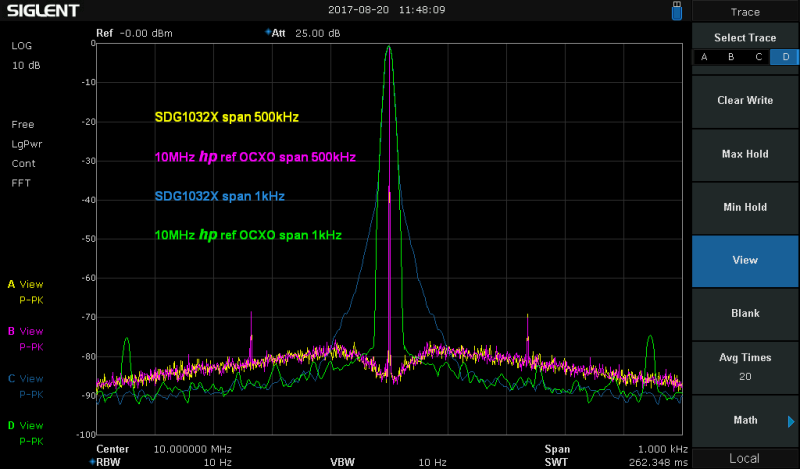
Here is one old image from tests I have done. There is lot of images but as told this time I do not have more available.

For understand better this image it need more explanations due to fact in this image there is two different SA settings in one image. I do not explain here but
blue trace can see part of SDG1000X near carrier "jitter". As can see, even with 10Hz RBW it can clearly see from around -35dBc that used tcxo and/or PLL is not at all best possible. (we know SSA RBW shape factor is bit under 1:5. Of course with 1Hz RBW, if used, it can see starting from much higher level from carrier but because 10Hz is enough for detect this and 1Hz RBW is really LOT of more slow and testing time is limited....) If I remember right it can clearly see full level using 1Hz RBW and long time peak hold. After then it can see it is more wide than 1Hz RBW shape is even there in carrier peak level. It have clock jitter and it is not much better than its specs. And do not directly believe it is better with External clock until enough accurate and reliable tests. Average freq is totally other question. Of course
it is as Ext ref is.
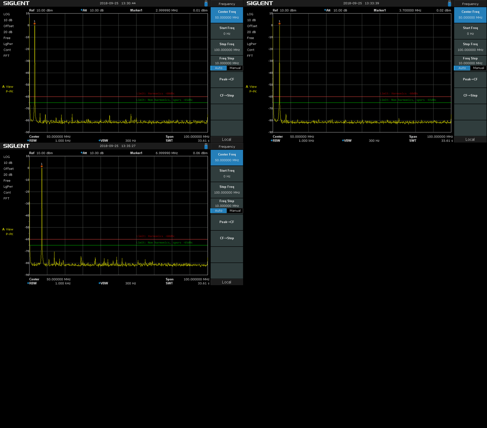
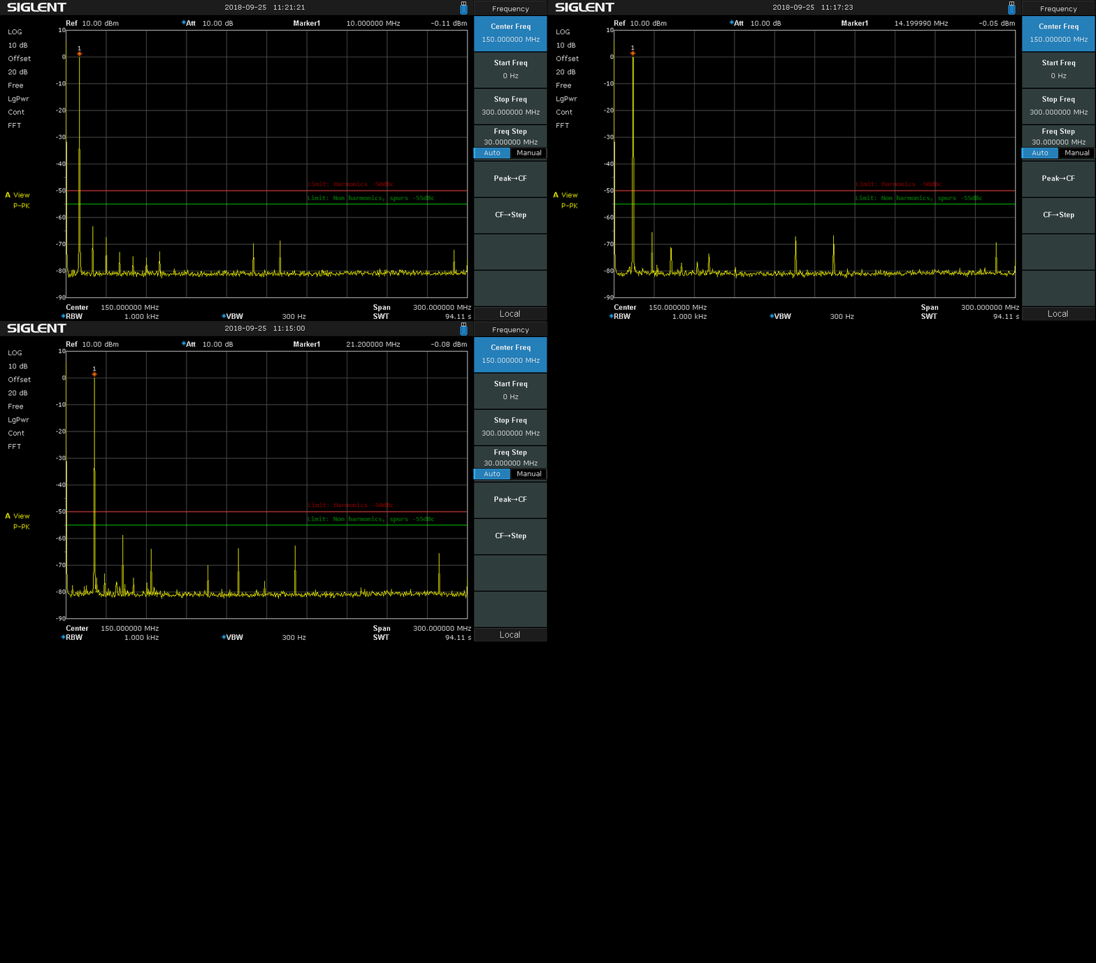
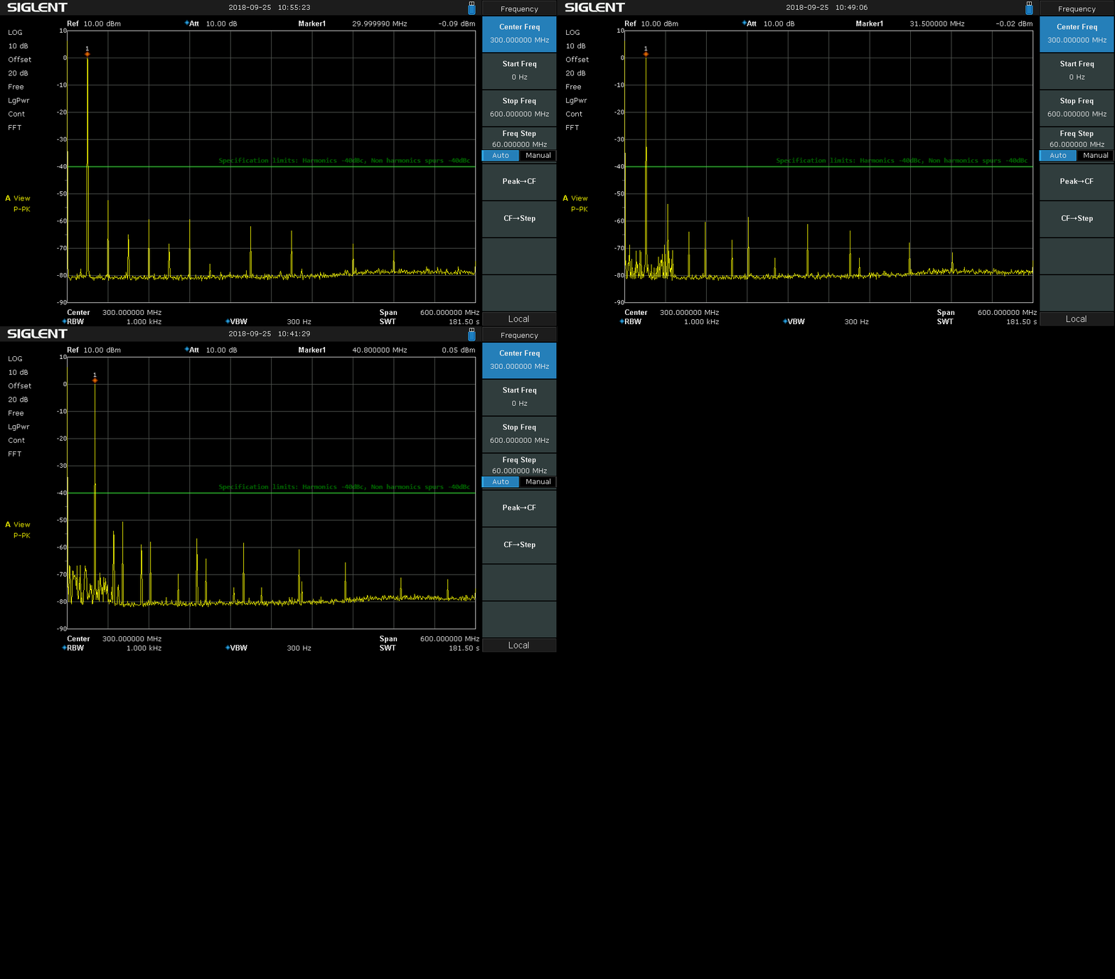
Because topic name is about harmonics here some images what are not whole OT.
Harmonics + non harmonics, 3, 3.7, 7, 9 and 10 MHz (note freq scale)

Harmonics + non harmonics, 10, 14.2, 21.2, 28, 30 MHz (note freq scale)

Harmonics + non harmonics, 30, 31.5, 40.8, 52 and 60 MHz (note freq scale)

In all images SDH1062X run with its own reference and SA run with its own reference what is LOT of better than SDG reference..
In First image compared signal is from HP High Grade OCXO what have very low jitter and pn. Enormous amount better short time than my any crap Rb or some short time crap poor trimble GPS. Only one I have is better than this, it is HP Symmetricom GPS with "famous" HP DOCXO what I have made even better than out from factory (better optimized Owen temperature control fine matched for this individual xtal used there) But this was cold in this time and not want wait one month... for stabilize.
About specs. If look SDG2000X its reference initial is more than 10 times better accuracy.
Then if look example some jitter specs. SDG2000X square (cycle to cycle) just 150ps RMS
But if look 1000X there is cycle to cycle 300ps + 0.05ppm of period RMS.
Now there is used 10MHz but delay is long. It is nearly same if use square with long period. So this part is here roughly in 2ns class RMS! (0.05ppm from 45000000ns is 2.25ns. and now, this is RMS, not Peak!
So my conclusion is, until know more: roughly this jitter you have detected now is more like in normal and somehow in specified class than individual failure.
Least if I see this kind of specifications I do not wonder if I find these results you have found.
Who ever have SDG2000X, it is different animal.
Attached your image with text what is based for my opinion. If I have mistake when I read your image please correct me.
