Note to reader: go to the bathroom and get something to drink and/or some snacks first. This review is long!Rohde & Schwarz RTM3000 reviewApparently I hit Rich's nerve and he had the Rohde & Schwarz branch in the Netherlands lend me one of these for a very long while to pick it apart:
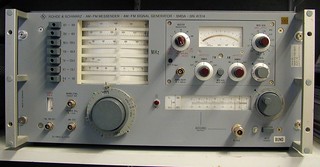
After a short trip to the Rohde & Schwarz office in the Netherlands there is finally some R&S gear in my lab again. The previous bit of R&S gear I had was this RF generator:
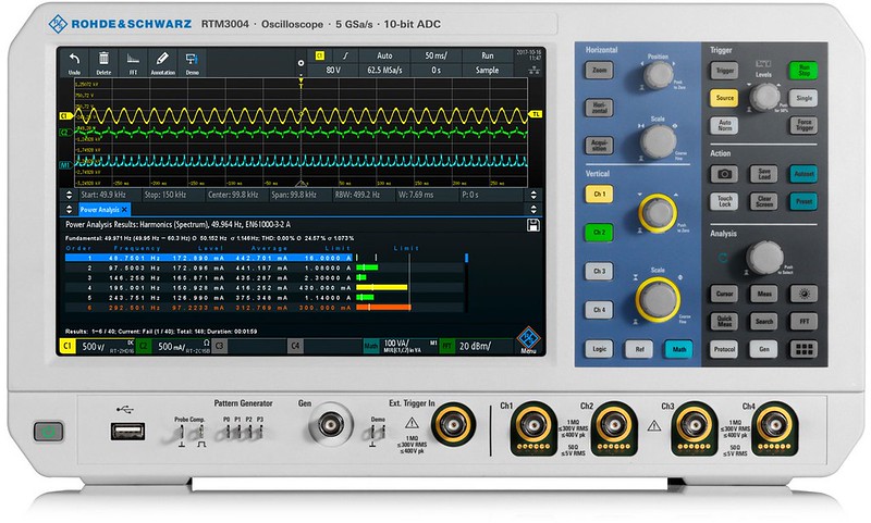
Anyway, back to the RTM3000. There is already a thread about the RTM3000 series but here is a quick summary with the most important specs:
2 or 4 analog channels
1 external trigger input
2.5Gs/s and 40Mpts memory with all analog channels enabled
5Gs/s and 80Mpts memory with half the analog channels enabled
400Mpts in segmented recording /history mode
100MHz to 1GHz (software upgradeable)
64000 waveforms/s peak
10.1" 1280x800 TFT display with capacitive touch screen.
Stackable math functions (stackable)
10 bit ADC
Options:
16 channel MSO option (2.5Gs/s and 40Mpts memory with all MSO channels enabled, 5Gs/s and 80Mpts memory with half the MSO channels enabled)
Segmented recording up to 400Mpts in total (700k segments/s peak)
Protocol decoding & triggering
Waveform & pattern generator
Spectrum analysis mode
Power analysis
All in all on paper the RTM3000 looks like it is a very versatile instrument and a big step up from the RTB2000 series. R&S seems to position this scope in the segment where the Keysight 3000T, Lecroy's Wavesurfer 3000z and Tektronix' MDO3000 series are also part of the regular crowd. I think R&S did well to have way deeper memory in the RTM3000 compared to the direct competing devices (especially Keysight's 3000T series). Also the RTM3000 has 10 bit ADCs and the highest display resolution of all so you can get more details of a signal on screen (which is one of the primary functions of an oscilloscope after all).
By the way: the '10 bit ADC' text on the badge is photo-shopped into the picture above. Real units don't have this text so don't be alarmed if the text is missing.
The RTM3000 comes standard with 500MHz passive probes and when the MSO option is ordered with two MSO probes. I would have liked it when a front cover is also included. The 4 channel 100MHz base unit (RTM3004) retails for around 4,500 Euro. The fully optioned one (1GHz + MSO and all other available options) is in the 18,000 Euro ballpark. There is a reasonably priced option bundle (the RTM-PK1 option which costs 2500 Euro) which enables all options except for Audio (I2S, LJ, RJ, TDM) triggering & decoding and the MSO. A 4 channel 350MHz model including the option bundle sets you back by around 9000 Euro. In my opinion the RTM-PK1 option bundle is a no-brainer and besides being useful it probably also increases the resale value of the RTM3000 when/if it is to be sold or traded in. It seems R&S has listened to the complaints that their options are too expensive compared to the competition (including the aggressively priced oscilloscopes from Chinese B brands). BTW it seems Batronix has a special offer where you get the new R&S FPC1000 spectrum analyser for free if you buy an RTM3000 series with a bandwidth of at least 350MHz.
I'll be using the term 'RTM3000' to refer to the RTM3000 series and 'RTM3004' when I refer specifically to the 4 channel model or the 4 channel unit I have here.
Test planIn order to get a good feel for what the oscilloscope is capable of I like to do a whole bunch of tests to try and get to the limits. I don't think I can test everything though. The user manual has over 770 pages and it is not long winded at all so there is a lot of functionality packed in the RTM3000!
Tests in random order:
- Bandwidth / aliasing
- Fan noise level
- Low level signal triggering
- Signal noise floor
- Overdrive recovery
- Math
- MSO inputs
- Protocol decoding, required over sampling and how much of the memory is decoded
- Long I2C messages
- Deep memory and decimating long traces onto the display
- Automatic measurements
- FFT function
- Spectrum analysis mode
- DMM application
- Search function
- Saving images and data
- Saving / recalling setup
- Cursors (outside screen?)
- Operating / using the scope
- Remote control abilities
- 10 bit usefulness
- Peak detect and roll mode
- Segmented recording and decoding
- Retaining settings
- Storing and manipulating reference waveforms
- Waveform generator
- Pattern generator
- Mask testing
- Self calibration/ self test
- Power analysis
- XY mode
- Waveforms/s
The secondary goal is to use the oscilloscope for a while to get used to the operation and in order to spot stability problems / usability issues.
Firmware version: 01.300 (although most of the initial testing has been done with version 01.200)
First impressionDespite the big 10.1" wide screen the oscilloscope is still compact. It has the same form factor as the RTB2000 series and the front cover seems to be exactly the same. With 39cm wide and 22cm high it doesn't take up too much desk space (the size is on par with my GW Instek GDS2000E and similar sized scopes like the Keysight MSOX3000T and Tektronix TBS2000 series). The biggest space saving comes from not having buttons around the screen and not having separate controls for each channel. The buttons are spaced relatively close together but not too close. Because the RTM3000 can be fully operated using the touch screen the buttons are more like a short cut keys to menus. I've found that most items showing a number (like the horizontal and cursor positions) can be tapped which then shows up a dialog which allows entering a number. That works way quicker than spinning a knob. The adjustment knob (in the analysis section of the front panel) and the horizontal position can use a better acceleration algorithm but due to the possibility to enter a number it doesn't matter that much. I rather enter a number anyway. Speaking of short cut keys: The top left corner in the display has eight short-cut-key positions which can be selected from 25 functions.
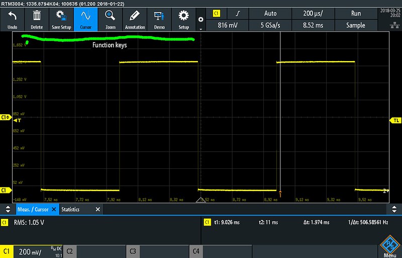
I would like to be able to have a choice from all the menu items here as well because some of them are useful to have as a short cut button on screen. On top of that you can also drag items from the main menu onto the screen creating even more short cut buttons although at the cost of screen space. This means the user interface can be highly customised to your own needs/wishes and maximise productivity. I'd almost say the physical buttons/controls are there to make the RTM3000 look like an oscilloscope but you don't really need them :-) I find myself using the touch screen the most and I'm only using the physical vertical and horizontal control knobs.
Despite the top menu bar and bottom status bar a large part of the display is taken by the signal display area. Horizontally there are 12 divisions, vertically there are 10 divisions. Due to the small dot pitch of the display vertical signal traces can become very narrow. The traces are fattened when the trace intensity is set to 100%. Still I like this way better than artificially fattened traces because fattened traces hide signal detail and waste screen space.
In case of multiple screens (like a list, FFT or measurements section) the height of the screen is freely adjustable so you can either have a big signal display area or show something else with more detail. I like this feature because it gives you a lot of freedom. I have been missing this on other oscilloscopes.
A while ago I had the chance to play a bit with an older (now obsolete) R&S RTO1000 series scope. This also has a touch screen but I found the user interface (screen layout and physical buttons) cluttered and disorganised compared to the RTM3000. It is clear R&S has created a new lean & clean user interface from scratch for the RTM3000 (and RTB2000).
The display itself is crisp with a lot of contrast. I have about 800 Lux blasting down from an overhead lamp. That doesn't make the display unreadable but I can see myself clearly in the display if I focus my eyes differently. At first I was afraid this would distract from using the oscilloscope but it turns out it isn't a big problem. A display with a matte finish would be better though. Another option would be to use a dark-on-light colour scheme. I have modified some of my previous scopes to have a dark on white colour scheme. After all a TFT screen doesn't have the disadvantage of masking dark areas like a CRT screen does. It may take some getting used to but hey, we all switched from light on dark to dark on light on our PCs a few decades ago!
What is nice is that a channel is automatically enabled and setup properly when a probe is plugged in (of course this only works with probes which can be detected using a probe ID pin). After using an input with a 50 Ohm source the channel reconfigures itself automatically when a 1:10 probe is attached. However there is a downside to this feature but more about that later.
As expected there is also a fan inside to keep the RTM3000's circuitry cool. R&S choose to use a relatively large fan (I estimate 92x92mm) running at a low speed. The noise isn't a nuisance even in a very quiet office. The BNCs on the front do get warm but not alarmingly hot. From the tear-down Mike (mikeselectricstuff) has done it is clear that the construction is different compared to the RTB2000 series. The main board is mounted parallel to the front and the BNCs are bolted to the chassis. The latter prevents plugging/unplugging probes and cables to flex the circuit board and also protects the circuit board in case the scope is dropped or bumped. Unfortunately these kind of accidents do happen and it is cheaper to bend a BNC back in shape than needing to replace the entire board and/or cause the oscilloscope to develop an intermittent fault.
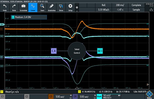
VerticalThe vertical controls allow setting an offset based on divisions or absolute voltage. A voltage offset keeps the signal centred on the display when changing input sensitivity. A division offset keeps the zero level of the signal on screen. The voltage per division can be adjusted in 1-2-5 steps or variable.
The traces can be moved across the screen by dragging it using your finger. Before moving a trace it must be selected by tapping it. If the scope can't figure out which trace you are pointing to by itself it presents the user with the following question:
One of the interesting things I have found during this test are the over range indicators. When the signal goes outside the range small markers pop up in the channel status bar indicating overshoots and/or undershoots. The analog Hameg oscilloscope I used at my first employer some 20 years ago had the same feature. I used it to find invisible spikes in signals. I'm pleasantly surprised to find this very useful feature has trickled up into the RTM3000! No I really can't write 'trickled down' here!
This signal has a small spike going outside the screen at the bottom:
One of the things added to version 1.3 is an auto scale button to the channel menu. I don't like it because tapping it by accident takes a while to execute and it messes up the channel sensitivity settings.
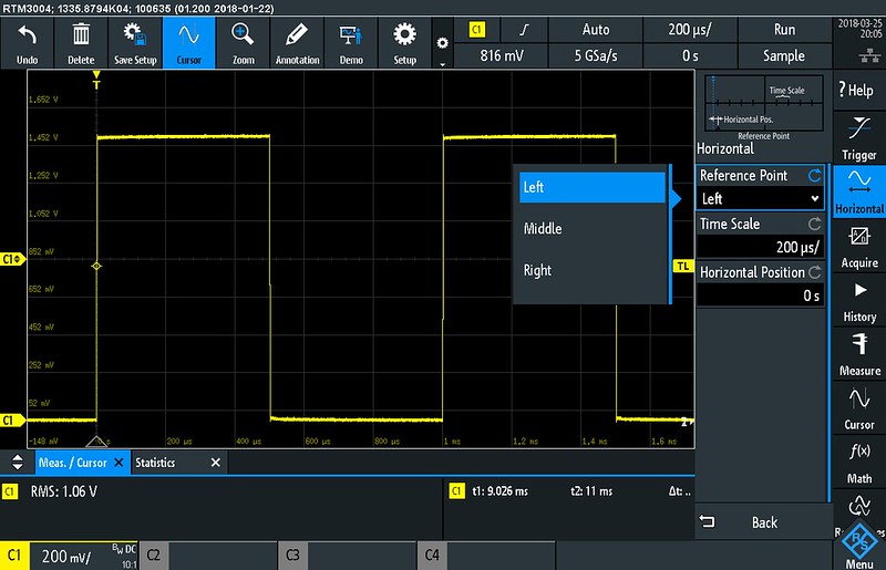
HorizontalThe time per division can be adjusted in 1-2-5 steps (the minimum time/div is 500ps) or freely variable. Having a freely variable time base is helpful to display a signal across the full width of the screen. The horizontal reference can be set to left, centre or right. I like to have the zero reference (=trigger point) at the left because in most cases the interesting part of a signal is after the trigger.
There is also a setting to adjust when the RTM3000 switches over to roll-mode. For some reason the selection at what time/div the roll mode is switched on is in the 'acquire' menu and not in the 'horizontal' menu. I would expect this setting to be in the horizontal menu.
Going over the specs in the datasheet I'm missing a trigger jitter specification.
Probes and accessoriesThe RTM3000 comes with probes for each channel (2 or 4 pieces). The probes are fixed 1:10 and have tips with a pogo pin (a spring loaded pin). Accessories include a BNC adapter, colour coding rings, ground spring, ground ring isolator and an extra tip.
All probes adjusted to show a nice square wave:
However... after putting the colour coding rings onto the probes it turns out I'm missing an indication for the channel colour near the input BNC connectors.
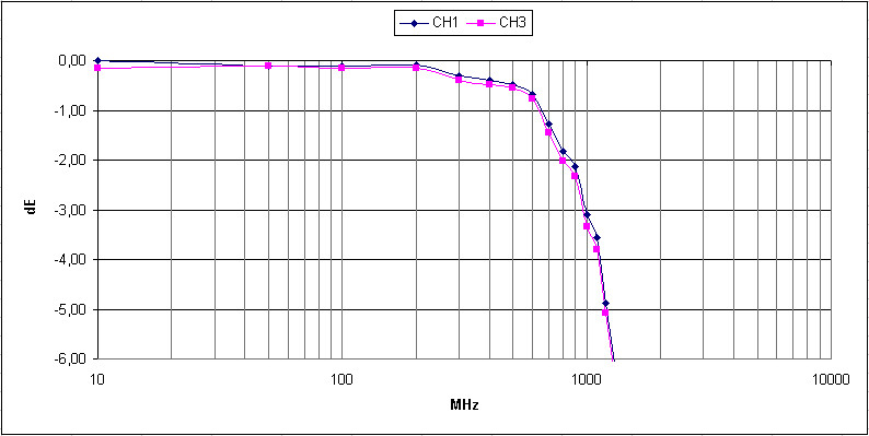
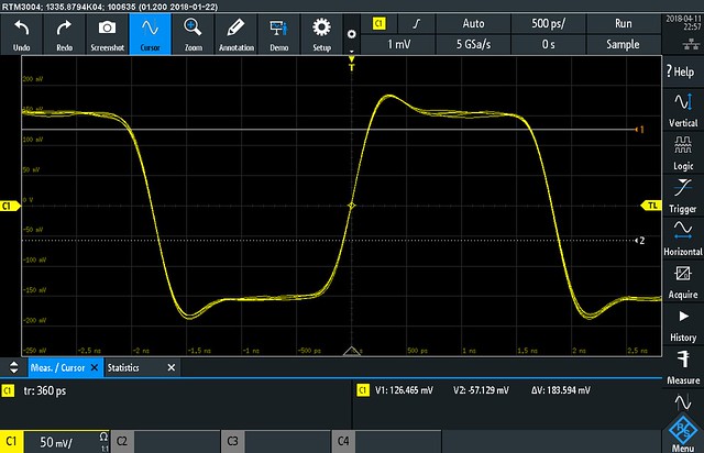
Bandwidth / aliasingTime to hook it up to my RF generator using some good Huber+Suhner RG223 coax to see what the frequency response and actual bandwidth is. With only channel 1 enabled (sample rate=5Gs/s) the bandwidth appears to be precisely 1GHz and not one Hertz more. I also measured the bandwidth on the other channels and channel 3 on my RTM3004 has a maximum bandwidth of 990MHz. The rise time on channel 1 is around 330ps so it seems the BW=0.35/rise time formula applies to the RTM3000 when the signal is sampled using 5Gs/s. The sin (x)/x reconstruction holds up nicely up to 1.1GHz at 2.5Gs/s which is what I'd expect so no drama here.
I've made some bandwidth graphs:
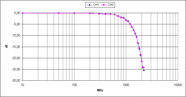
During testing with higher frequencies I also found another interesting phenomenon. When I input a signal above 1GHz (say 1.7GHz) the amplitude stays the same in the 500uV/div to 20mV/div vertical sensitivity ranges! I can change the sensitivity on the oscilloscope or amplitude on my generator: it doesn't make any difference. What the hell is going on here? At 505 MHz (odd frequency to rule out aliasing effects) everything seems to be normal.
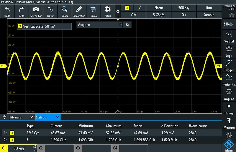
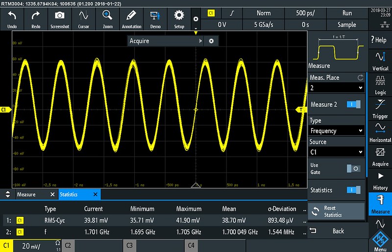
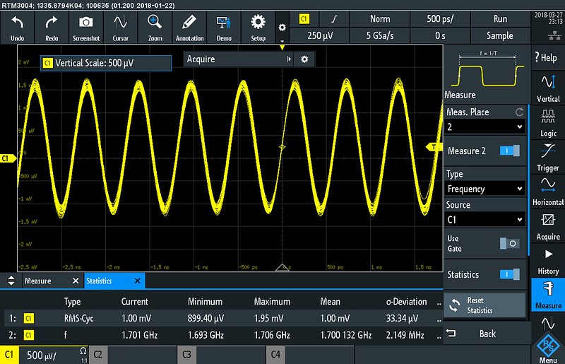
And no, the problem isn't sin(x)/x reconstruction (note the sample rate!). The same happens in linear interpolation mode and my RF generator is also OK (checked to make sure).
According to R&S this effect is caused by a limited slew rate in the pre-amplifier stage. I assume this pre-amplifier is necessary to amplify low level signals so they match the ADC's input range.
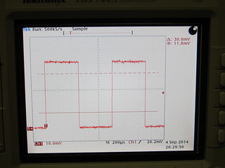
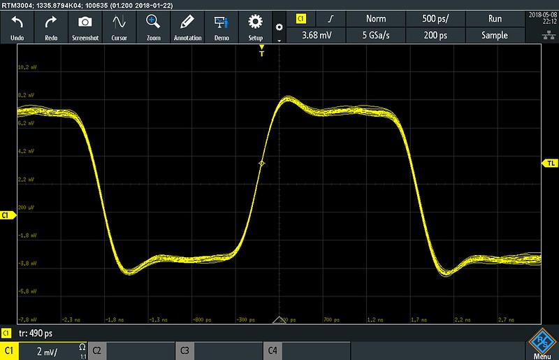
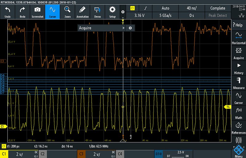
Because of this effect I wanted to investigate a bit deeper to see if this would have an effect on actual measurements. I decided to feed a 275MHz square wave with sharp edges from an ADF4351 based generator with a 50 Ohm output into the RTM3000. A 275MHz square wave has strong harmonics at 825MHz and 1.375GHz but still looks like a square wave when using a 1GHz bandwidth. I used a 200mVpp and a 10mVpp amplitude. The latter is the 200mVpp signal attenuated 20 times (26dB) to simulate using a 1:20 low-Z passive probe.
200mVpp:
10mVpp:
To have some comparison with another oscilloscope I also measured the same signals on my Agilent 54845A (1.5GHz bandwidth):
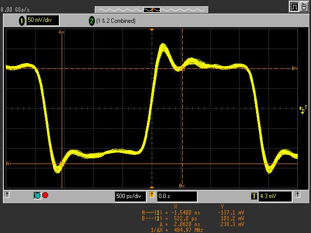
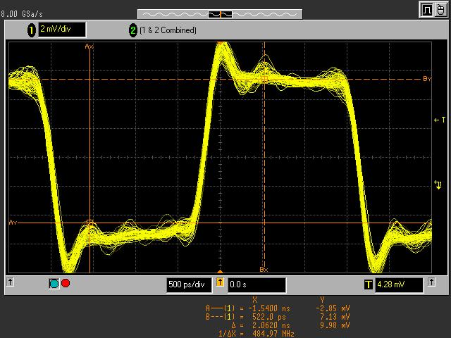
All in all it doesn't seem like a big problem after all.
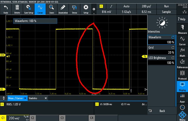
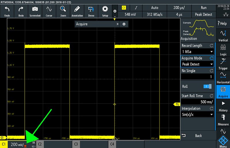
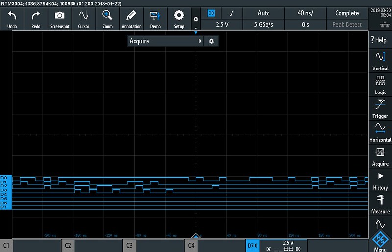
Acquisition modesCompared to other oscilloscopes the RTM3000 has a lot of different acquisition modes. Besides sample, peak-detect, average, high-res and envelope mode there are also combinations of acquisition modes like high-res + average, peak-detect + envelope and envelope + high-res so you can really tailor the acquisition mode to your needs. Note that envelope and peak-detect are closely related. So related that on Japanese scopes peak-detect is usually called envelope mode but that is a different story. On the RTM3000 peak detect lets the ADCs run at full speed and you get the minimum and maximum in the sample interval. Envelope mode on the other hand uses multiple acquisitions (the number of acquisitions is adjustable - say it is X -) and shows the minimum and maximum of the last X acquisitions. I like that the acquisition modes allow some mix & match. I've been missing that on other oscilloscopes every now and then.
A good test when it comes to acquisition modes is to check whether peak-detect works in roll mode. For this I'm using 16ns pulses which are output once every second. The RTM3000 has no problem catching these even when set to a short record length (5kpts). Of course the exact shape of the pulses gets lost but at least you can see something is there and investigate further.
In average mode there is an issue though. When using averaging mode the averaged trace disappears when changing the time base in stop mode. I did not expect that but I have seen it before on other oscilloscopes so I guess it is something software developers working on oscilloscope firmware tend to overlook. This will need to get sorted though.
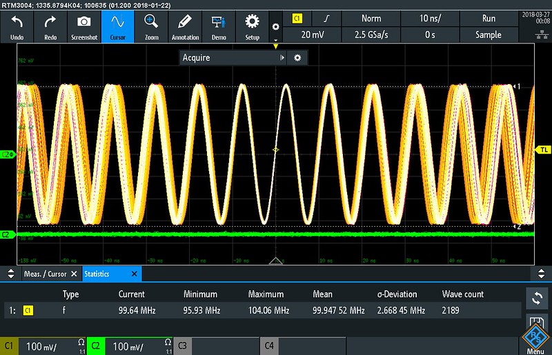
TriggeringIn short: the trigger works very well. With 1 channel enabled I can get a stable trigger on a 2GHz sine wave. Using a 10MHz signal and bandwidth limit set to 20MHz the RTM3000 is able to trigger on signals as small as 350uVpp with the trigger set to the most sensitive setting. By the way: the trigger status also shows how much time has elapsed since the last trigger. Not bad!
When in auto-mode there is a short delay before the RTM3000 goes back to free-running mode after a signal caused a valid trigger. This used to be a typical Tektronix feature but other manufacturers seem to copy it nowadays.
What I'm missing is a small trigger frequency counter somewhere in a corner of the screen. There is a trigger frequency counter (which also shows the period) available but that sits in a big windows which overlaps a significant part of the display.
Signal noise floorSignal noise floor is important to look at when it comes to oscilloscopes intended for general purpose use. Some older high bandwidth scopes have so much noise that they become less useful for looking at lower frequency signals especially when it comes to small details of a signal or when making accurate cursor measurements.
I'm not looking for how to get the lowest noise here but just to get an idea of what to expect in a normal usage scenario. For this test I selected a 1Mpts record length in order to get a lot of samples.
500uV/div 50 Ohm full bandwidth:
500uV/div 1M Ohm full bandwidth:
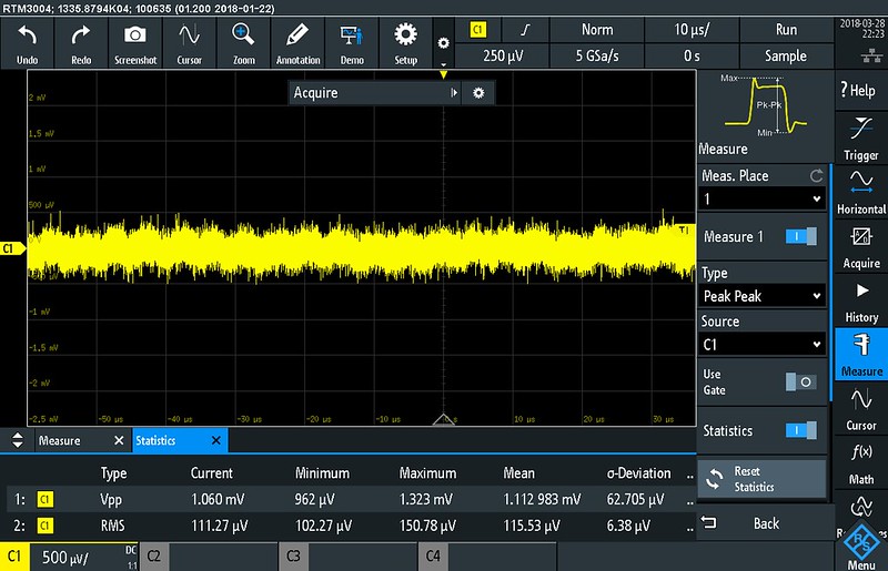
500uV/div 50 Ohm 20MHz bandwidth:
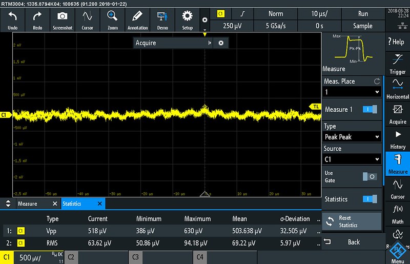
500uV/div 1M Ohm 20MHz bandwidth:

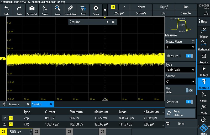
This looks all nice and dandy but 500uV/div isn't a setting you'd use daily so let's take a look at the noise level with full bandwidth at a more useful V/div setting with a probe attached:
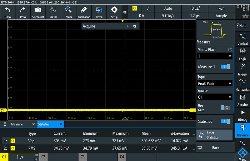
At least that doesn't result in a wide band of noise across the screen so thumbs up!
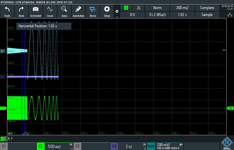
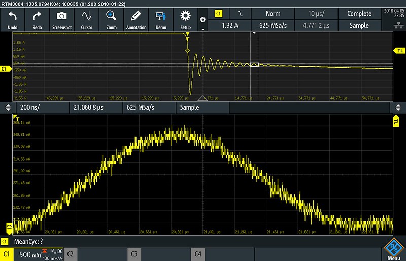
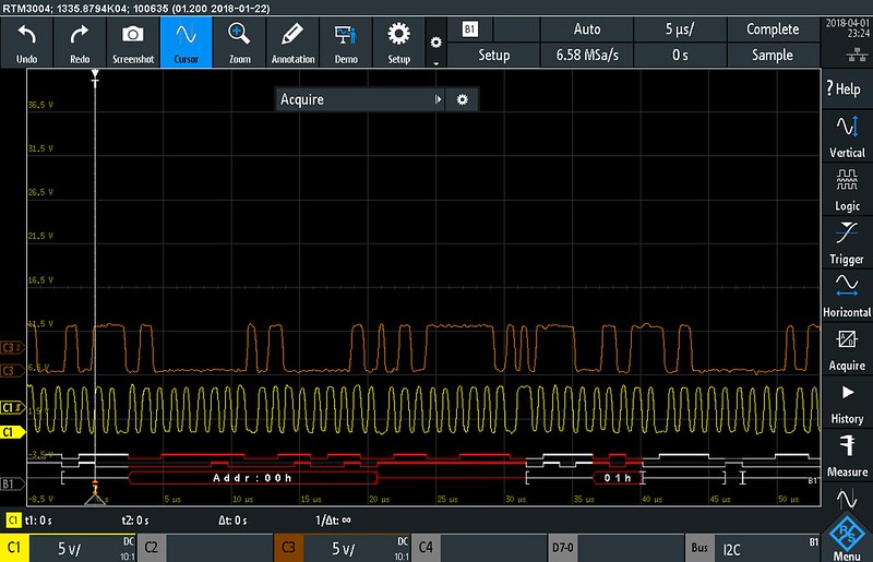
10 bit usefulnessOne of the cherries on top of the RTM3000 is the 10 bit ADC. Now how useful is having a 10 bit ADC instead of an 8 bit ADC? One of the limitations of getting a large dynamic range from an ADC is the sample clock and sample&hold jitter. The higher the sample rate, the higher the signal frequency and the larger the number of bits the smaller the jitter must be. To get 10 bits at several Gs/s the jitter needs to be in the femtosecond territory. All in all it is unlikely you can get 10 bits at 5Gs/s. So far the bad news. Now on to the good news. If the signal is bandwidth limited the clock jitter isn't that important and you can get more bits more easily. To show this I have measured similar signals using the RTM3004 and a GW Instek GDS-2204E.
The signal comes from a 125 kHz RFID write operation which has a high dynamic range because the write pulses are very large compared to the received data.
Zoomed horizontally on a write and a response:
Now zoomed in vertically:
I think the screen shots speak for themselves. The small part of the signal can be enlarged to study it in greater detail on the RTM3004 but on the 8 bit scope zooming in vertically to see more becomes futile quickly.
The deep memory also makes a measurement like this easy. There is no need to really trigger on a specific part (shape) of the signal. Just press stop when you see the signal of interest and you have all the details you need.
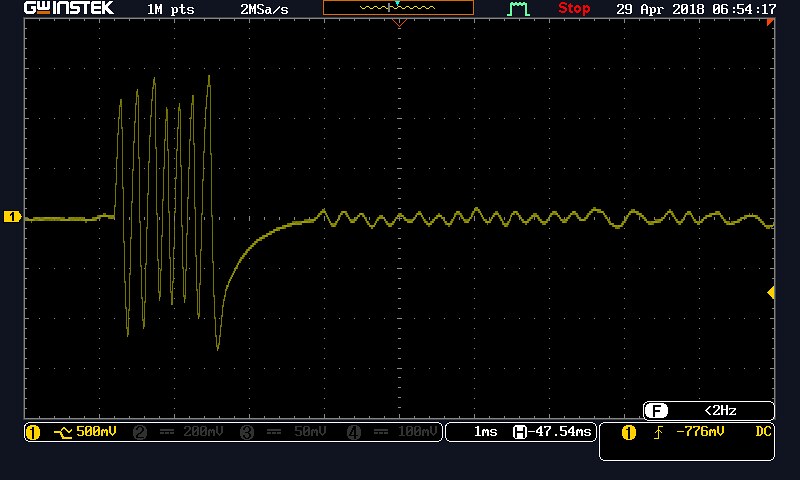
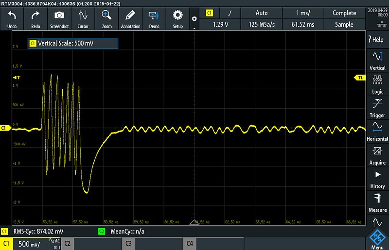
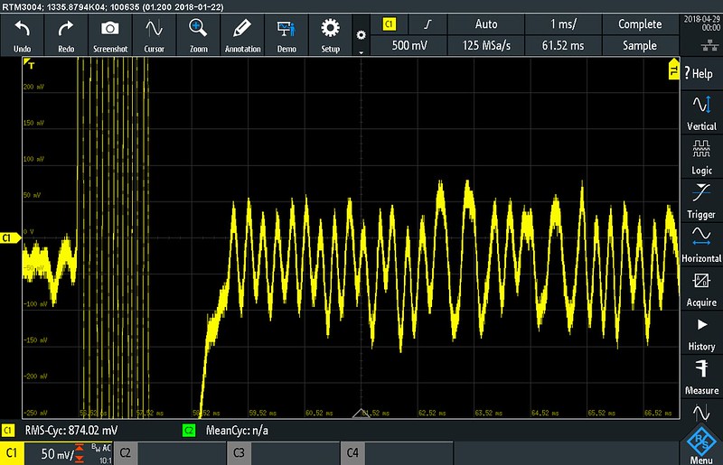
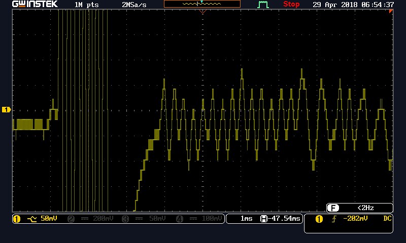
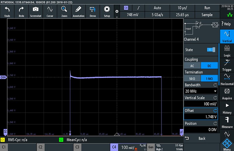
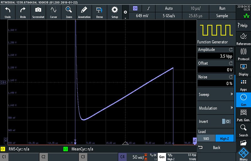
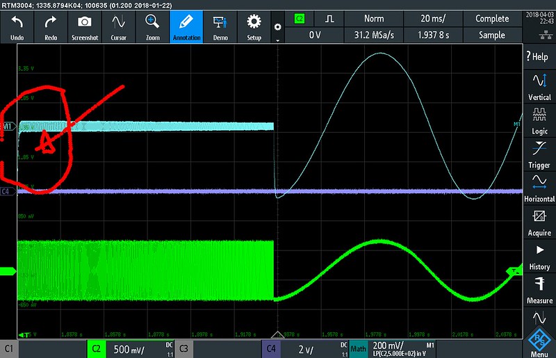
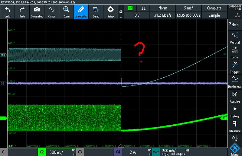
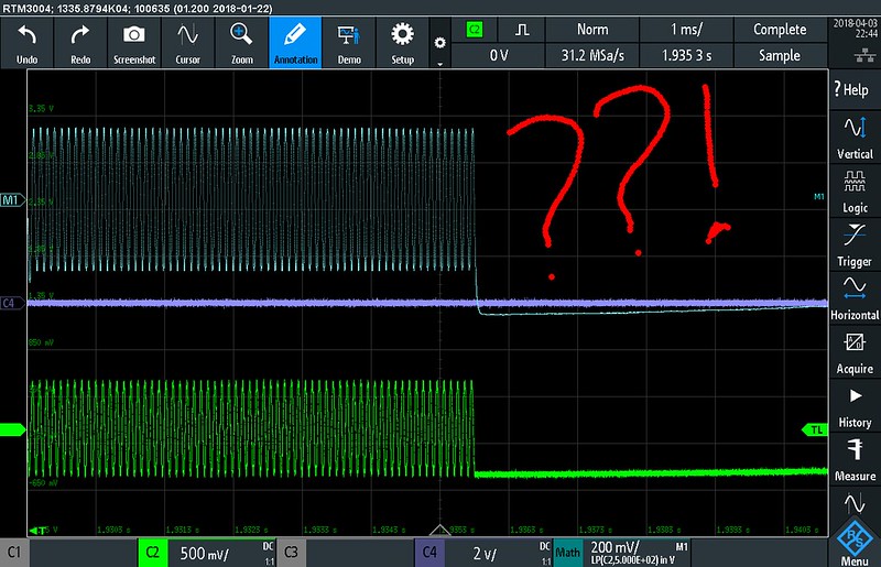
Overdrive recoveryIt's always interesting to see what happens when the amplitude exceeds the input range. For this I used a 3.5Vpp square wave from the generator:
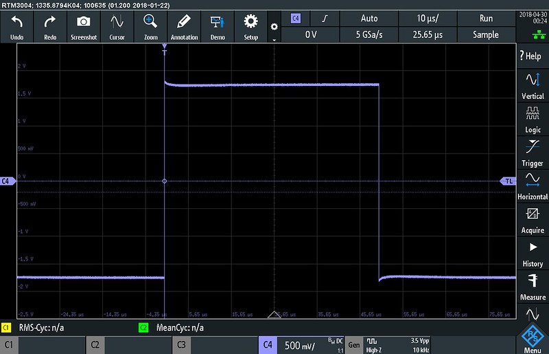
At 100mV/div I can still get a nice waveform but at 50mV/div (I can hear a relay click when switching between 50mV/div and 100mV/div) the signal gets severely distorted.
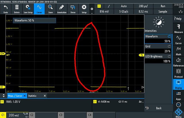
 Display modes
An interesting feature of this scope is that the colour grading method (or default trace colour) can be selected separately for each channel. I find this a very good choice. On other oscilloscopes where the colour grading setting applies to all channels it is easy to lose track of which channel is which.
There are several colour palettes to choose from (temperature, fire and rainbow) and by setting a trace to inverse colour seldom occurring events can be highlighted.
Of course the persistence can also be adjusted. There is one odd thing though: the persistence continuous to fade out when the stop button is pressed and the signal should be frozen. Also the infinite persistence trace disappears when the cursors are enabled/disabled. That shouldn't happen! What if you let the scope run for several hours and you forgot the enable to cursors?
Saving imagesSaving images can take up 10 to 15 seconds but it is not consistent. When it takes long to save an image the signal update rate slows down a few times during the operation so it seems saving an image is a heavy burden on the CPU. I have definitely seen faster image saving and I would expect saving an image to be done in a few second tops on a modern oscilloscope. I've used the same USB stick (from Kingston so no cheap crap) I use for all my test equipment so that can't be the problem. After further usage it appears that doing a screen shot works fastest (a few seconds) with the acquisition stopped. After a screen shot a message appears on the screen which can be tapped (clicked on a touch screen?) away.
Remote control abilitiesThe RTM3000 has a USB and Ethernet connection. USB can be used in three different modes: TMC (test & measurement class), VCP (serial port) and removable storage using MTP (media transfer protocol). TMC and VCP allow doing remote control using SCPI commands. I like the fact that R&S also included VCP (serial port) because a serial port is among the easiest and hassle free interfaces to use. Unfortunately the removable storage doesn't work out of the box on my Windows XP and older Linux system. On Windows 7 and the newest Debian Linux it does work out of the box and it allows to access the RTM3000's internal flash storage, an on-demand storage (where files contents like a screen dump is created on-the-fly) and a non-volatile storage to transfer temporary files.
The Ethernet connection has several functions as well. It can be used for VXI and SCPI over telnet for remote control but the RTM3000 also has a built-in web server. I played a bit with that and with Firefox (version 59 on Linux) I have no problem whatsoever to use the web interface. The web interface allows making screen shots, controlling the RTM3000 remotely through a virtual front panel and last but not least testing SCPI commands. The latter is very useful for testing commands while developing your own software. IMHO R&S made the right decision to go for a web interface and not develop a separate software package. A web interface works on every reasonably modern computer with a recent browser. I can even control the RTM3000 from my Android based Smartphone (within the limits of a small display of course but it works).
The user manual has a comprehensive list with SCPI commands and also shows a few examples on how to set the RTM3000 up remotely and retrieve data.
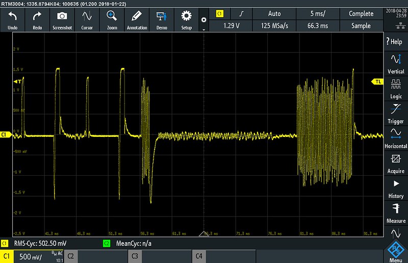
MeasurementsLike many modern DSOs the RTM3000 has a wide variety of measurements. When selecting a measurement there are clear thumbnails showing what the measurements do. After adding a measurement the result is shown in the bottom left area of the screen. By touching a measurement you can change the type and the source channel. That is a huge improvement compared to other oscilloscopes I have used so far. On those existing measurements need to be removed and recreated to -for example- use a different source channel. On the RTM3000 you can simply change an existing measurement. Statistics are also available which show the average, minimum, maximum and standard deviation. With the menu at the right side collapsed (tap the R&S logo) there is a button to reset the statistics at the right side of the statistics box.
When the gating is enabled a blue bar is drawn over the part of the acquisition which is used for the measurement.
When doing some other testing it seems the measurements are taken on sub-sampled data and not directly from the acquisition memory. Only when I zoom in the information becomes available. In this case I scroll through a frequency sweep and use the gating to find the frequency for the section currently under the gating bar. This seems like a perfectly legitimate use to me but I get no reading from the measurement.
Something similar happens for a rise-time measurement on a square wave. At some point the measurement value is no longer available (after being marked as inaccurate). At least the measurements don't show bogus values.
Zoom modeThe zoom mode allows to zoom in both horizontally and vertically (even below 500uV/div) so every detail of a signal can be shown.
 MSO inputs
The 16 digital inputs are divided over two 8 bits pods. The MSO pod is connected to the RTM3000 through a sturdy but flexible ribbon cable with 29 pin HDMI type B connectors on each end. Even though the connectors are on the side of the oscilloscope they don't stick out very far. The pod itself is a separate box and because it gets warm it seems to be an active probe. An LED indicates which channels (0-7 or 8-15) are connected to the logic probe POD. Here is a picture with the RTM3000 MSO pod and the output pod from a pattern generator.
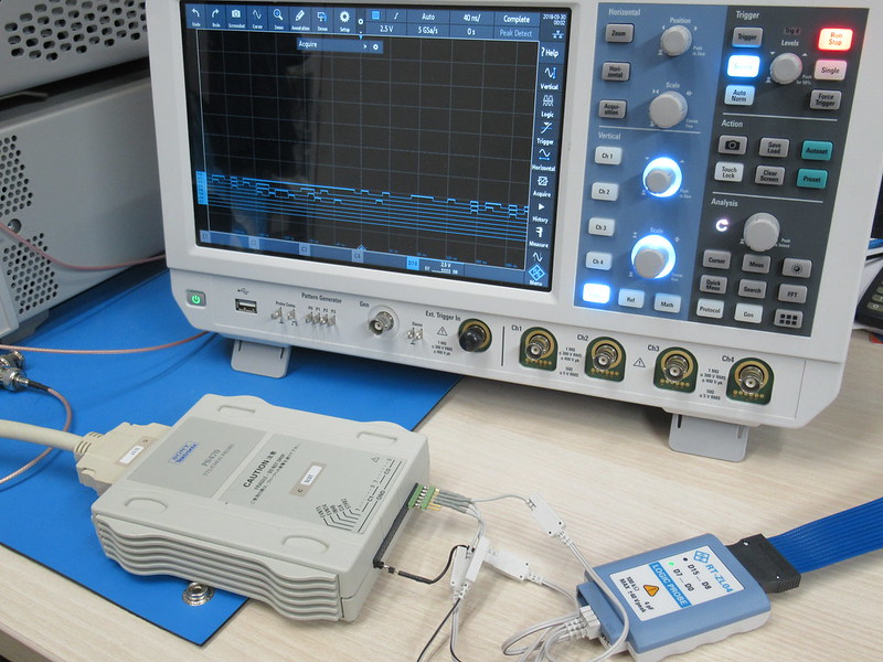
The connectors are standard IDC connectors so they fit well on standard 2.54mm (0.1") header pins but are less suitable for thinner pins or wires.
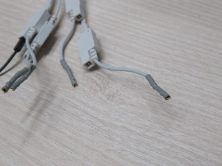
A set of micro grabbers (good down to SOIC packages) is also included.
Using the menu the digital signals can be set to small:
... or full screen:
However the digital channels can be scaled in smaller steps using the 'Scale' knob and the vertical position knob can be used to move the digital signal. It would be nice if the larger/smaller buttons in the menu could do several steps instead of only small or large.
One thing that I was wondering about: are the MSO probes hot-pluggable? HDMI connectors seem to be designed for hot plugging and there is no explicit warning against hot-plugging the MSO probes in the manual. Only one way to find out: try it! And YES hot plugging the MSO probes works just fine! Perhaps this seems logical to many people and not a big deal but I have come across quite a few pieces of equipment which don't allow hot-plugging active probes/pods so I'm a little cautious.
A nice feature is the adjustable hysteresis. One of the problems I had with an MSO from Agilent was that it would create false pulses because the hysteresis was too small to deal with a slow edge from an I2C bus which in turn (annoyingly) disrupted protocol decoding.
One question remains though: where can one buy HDMI cables with type B plugs? Just for kicks it would be interesting to try and see if the MSO cables can be replaced with off-the-shelve cables or not. Longer or shorter cables could be helpful in some cases depending on how your work bench is setup. On my workbench I have the oscilloscope at the right side of my work area because I didn't have enough depth in front of me for the vastly deeper larger oscilloscopes I used to have. But for this setup the MSO cables are slightly short.
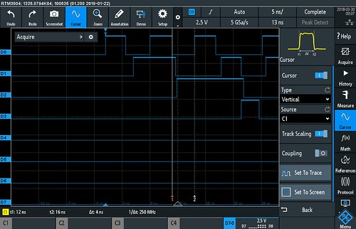
CursorsWhen it comes to cursors there seem to be two ways of doing things: keeping the cursors confined to the screen (the Keysight scopes I have used so far do this) or allow the cursors to be placed outside the screen. The latter allows doing way more precise measurements on signals. The RTM3000 falls in the category where the cursors can be placed outside the screen so all is well. Tapping the cursor positions on screen allows entering a position (time offset from the trigger point).
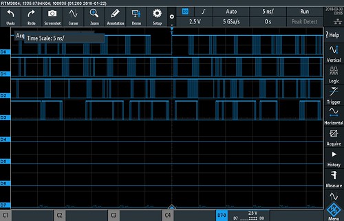
DecodingThe RTM3000 has 4 decoding busses in total where each bus can decode one stream. For example: decoding the RX and TX from a UART means using 2 decoding busses. For this test I pulled out my new toy: a digital pattern generator. With its maximum bit-rate of 250Mbit it can easily create a 62.5MHz I2C signal:
In order to tell the I2C bytes apart I added a small delay between each byte.
I2C decodingTriggering on an I2C start seems to be no problem. When I screw up the I2C signal on purpose the RTM3000 spots a problem and marks the signal red.
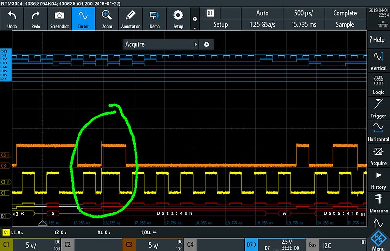
One clock pulse missing:
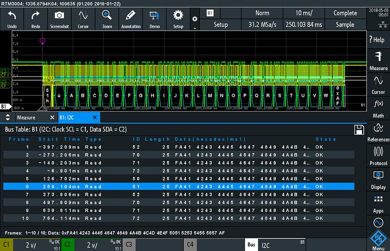
Also decoding long I2C messages aren't a problem. The message is truncated in the list but the content is shown at the bottom of the screen as well. Of course the area is limited. If you want to see even longer messages then you'd have to save the bus list to a CSV file. I have not tried to upper limit but 64 bytes wasn't a problem.
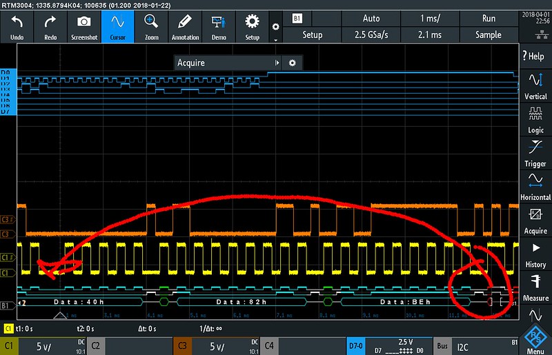
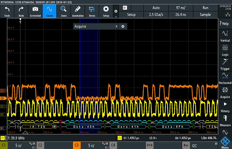
Time for some over sampling tests... I generated a 1MHz I2C signal and checked at what sample rate the RTM3000 starts to decode properly. With a memory length of 40Mpts the minimum sample rate is 62.5Ms/s. That means an over sampling factor of 62.5. With a record length of 5kpts the minimum sample rate to get a steady decoding result is 41.7Ms/s. That is rather disappointing because the signal still looks like an I2C signal at much lower sample rates. I get that some filtering is required for protocol decoding to suppress false edges but the over sampling ratio could be much smaller (like 10 or so).
On the upside: according to the datasheet I2C decoding works up to 10Mbit/s but from my testing it seems I2C decoding works well up to 40Mbit/s (40MHz clock). By the way the digital signal used for the decoding can also be shown as part of the bus (enable/disable 'bits' item in display menu). The picture above shows that the digital signal is different compared to the actual (analog) signal so at least it is visible that the sample rate is too low for decoding the signal properly.
 SPI decoding
On to SPI decoding. In order to decode both MISO and MOSI signals I need to configure 2 busses. Because I had bus 1 already in use for I2C I had to use bus 3&4 to get the MISO and MOSI data streams. When I selected bus 2 I could only get one data stream decoded. With the SPI rate set to 10MHz the minimum sample rate is 312Ms/s which means an over sampling factor of 31.2. When the sample rate is set to 2.5Gs/s the maximum SPI clock rate I can get to decode is 62.5MHz (on the digital inputs) which is much higher than the specified 25MHz.
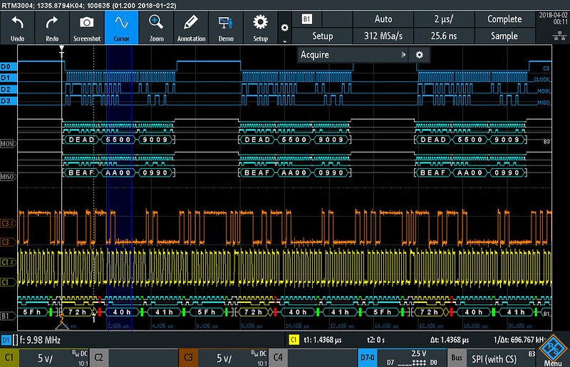
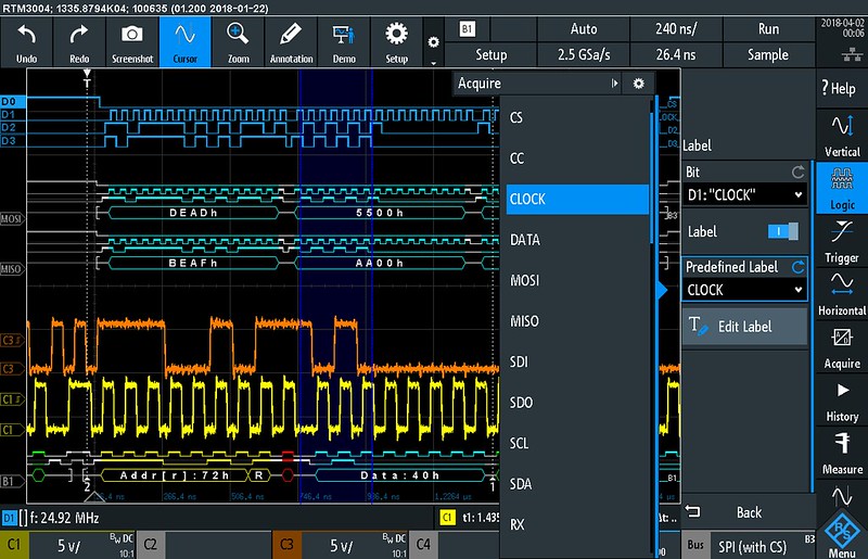
Yes, I have enabled the gating on the measurement to show the data rate for the I2C or SPI bus! The blue bar shows which part of the signal is used to for the measurement. It is also possible to add labels to the digital channels. There is a whole range of predefined labels which you can choose from.
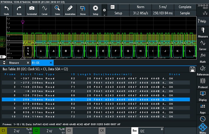
With both I2C and SPI decoding enabled let's see what the bus listing does with a continuous stream of back-to-back messages at the maximum memory depth... The listing shows both I2C and SPI messages. It seems we've got about 16700 I2C messages and 32000 SPI messages. Good! Not every scope I have come across can store all the messages it can decode from memory. It is no surprise an oscilloscope in this class decodes the entire memory. When browsing through the list a push on the Analysis button takes you to the start of the message on screen. A purple marker shows where the message starts. The amount of display space taken by the list display and the signal display can be chosen freely by swiping the white opposite arrows on the left up or down. Pretty neat!
Another neat feature is that non-ASCII characters are shown as hex:
 UART decoding
Some screen shots from UART decoding:
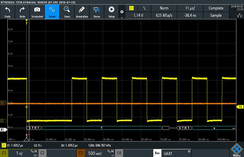
The start and stop bits are clearly marked.
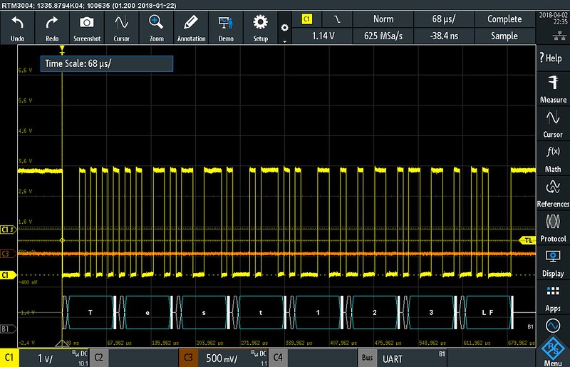
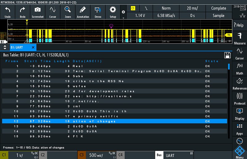
Of course the data can be displayed as ASCII (but also hex, binary and hexadecimal). The UART decode message list has an interesting feature: characters which are send back-to-back are displayed on the same line. I have not found a way to set a time-out though so it might not always work but it is a major improvement from other scopes I have experience with. A nice addition would be to set a frame terminating character (or sequence) but I'm not complaining.
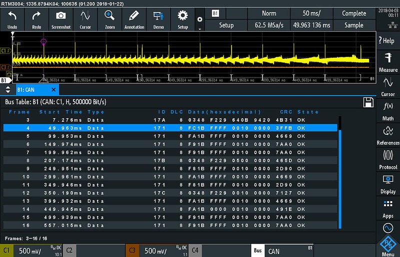
 CAN decoding
It is getting boring. CAN decoding also seems to work well with this less than ideal signal.
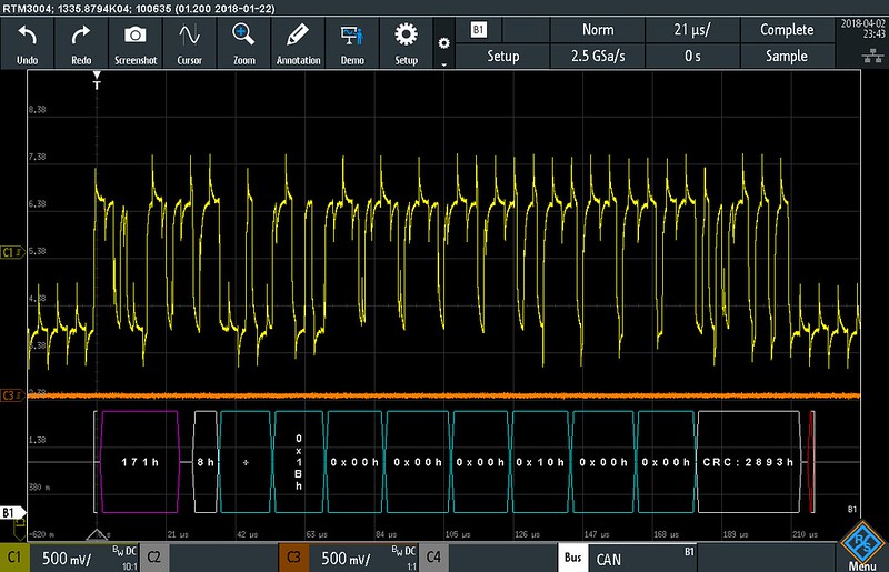
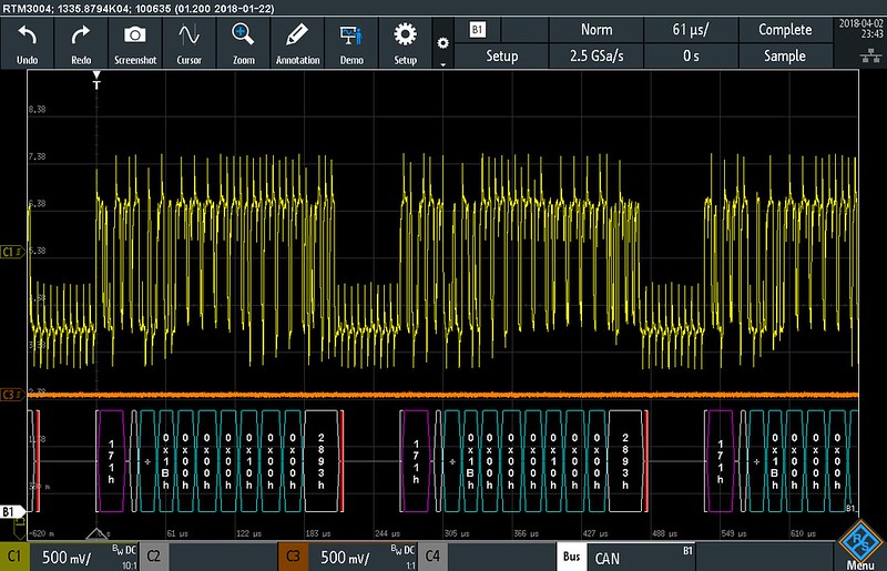
Note how the data gets rotated 90 degrees to fit the height of the bus decoding when the bus display is made taller. Nice!
 Some remarks about decoding
Like on Keysight scopes you can't change the decoding parameters after doing an acquisition. The decoding seems to be done in parallel with the acquisition into a separate memory. I don't like this because you can't fiddle with the decoding parameters after doing an acquisition to see which settings work right. For situations where you have two different bit rates and/or parameters (yes, this does occur) you can use two decoder busses in parallel each set to a different bit rate and/or configuration.
With decoding enabled the maximum depth is 40Mpts and the maximum sample rate drops to 2.5Gs/s. I'm not sure whether I can agree with this choice. On one hand given the bit rate limits of decoding it doesn't make sense to have the 5Gs/s sample rate but more memory depth would have been nice. On the other hand the limits make it harder to look at a high speed signal in detail while doing decoding. A usage scenario could be testing a circuit which has a SERDES (where a high speed serial stream is converted to and/or from a parallel bus) and using the decode feature to print a list with data and/or trigger on a bad message. At 2.5Gs/s the upper frequency limit for having a signal visible is about 1.1GHz.
What I do like about the decoding is the 'find threshold' button. Just tap the button and the RTM3000 finds the right threshold. It even worked on the less than ideal CAN signal.
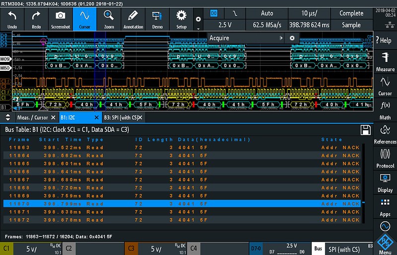
Something else I wanted to take a look at is how decoding works together with segmented recording. One of the things I liked about the Agilent MSO7104A I used to own is that it can list the decoded data from all segments. This means you can set a trigger for a specific message and cram as much relevant data into the memory as possible using segmented recording. Unfortunately the RTM3000 doesn't do that. In segmented recording (history) mode the 'bus list' only shows the decoded data for the currently selected frame and not data from all the recorded frames.
Note: keep in mind that the signals I used for testing SPI and I2C have picture perfect timing so in real circuits the maximum bit rate that can be decoded for SPI (I doubt I2C will have any issues) may be lower.
MathAll you need is math.... The RTM3000 doesn't have the free form math bonanza the GW Instek 2000E series offer but it still has a decent amount of abilities. There are 5 math traces (M1 through M5) which can be stacked sequentially. M2 can use M1, M3 can use M2 and/or M1, etc. Among the usual operators (add, subtract, multiply, divide, etc) the math traces can also do low-pass or high-pass filtering. By stacking the filters using two math traces it is also possible to create a band pass filter. So far the theory. I tried some math equations and I noticed that the math traces seem to use decimated (screen) data instead of the actual data. This leads to wrong results on some signals.
FilteringFiltering can be very useful for developing DSP algorithms and cleaning up signals in general. Therefore I wanted to dig a little deeper into this feature. I applied the low pass filtering on a frequency sweep. Unfortunately there is some funny business going on when zooming in on the signal: the filtering stops working!
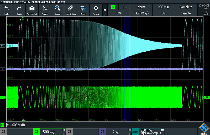
A filter initialisation artefact which could be hidden if the filtering started a few samples before the left side of the screen:
But when zooming in more the filtering stops working:
Changing the memory depth doesn't help.
Also the filter could roll off a bit sharper. However what is more problematic is that the way it sits now the filtering is not really useful mainly because the math trace uses decimated data but also because of the flaws. In my opinion R&S should move the filtering into the acquisition hardware somehow.


