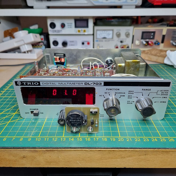
I am working on the repair and re calibration of a Trio DL-703. The meter had been modified and connections were missing and some PCB tracks badly reapaired. So basically it was a non runner.
The PCB from my meter from the top:
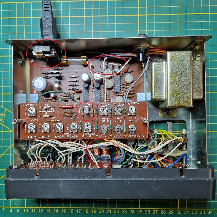
See red circles. There are 2 common mode coils, one in the mains connection and one at the input of the meter directly behind the buses. This is not original, I find the last one especially strange. There is a replacement capacitor on the 'potmeter' PCB. I don't think the mains strapping is as it should be. It can also be seen that the display print has some broken paths and therefore not all segments light up anymore.
The PCB from my meter from the bottom:
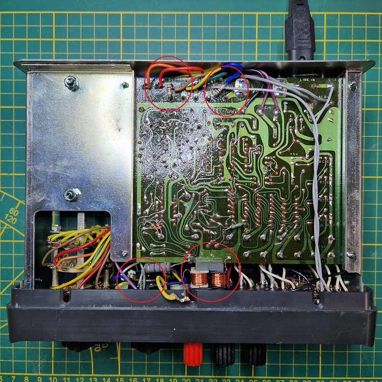
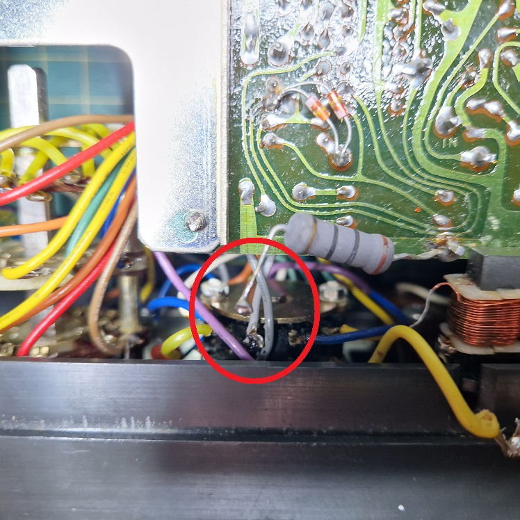
There are 2 additional resistors in series with the mains connection. The input of the mode switch is loose, it should be connected to the red banana. The shunt resistor, which was also defective if forgotten, is also loose. I think it should be connected to the white connection on the mode switch, see below:
So I got started with the repair. First I removed the common mode coil behind the banana buses and soldered the red bus with a red wire to the mode switch and also the black bus with a black wire to ground. Then the transformer connection wires for the primary side were drawn up, the diagram was drawn up and some soldering was embellished. Fortunately, I knew from my friend bjokal that it was normal for there to be 100Ω resistors between the primary winding, and that this did not have to be removed.
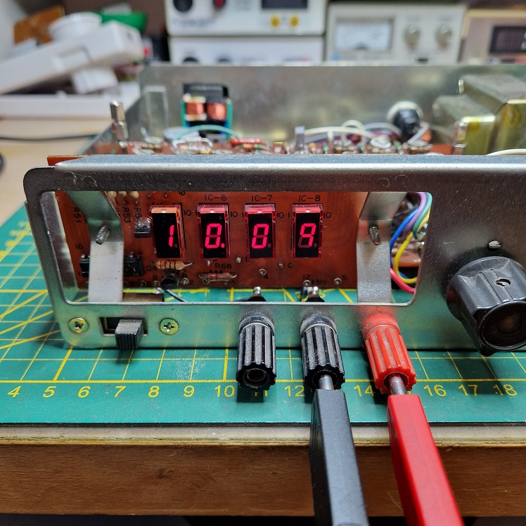
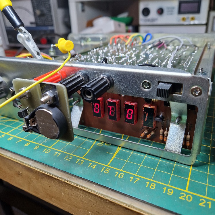
I also repaired some soldering on the display PCB and applied the mains voltage with this result:
Then next it was to fix the shunt for the current range, there is only one current range 200mA for this meter, fused at the back. It contained 630mA, so I made it 200mA again and checked whether I had connected the right wire to the right contact of the mode switch by connecting a 1mA source and with success:
Wire soldered and the meter turned over again and the same test:
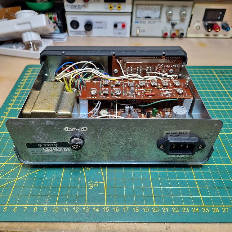
The mains connection is originally fixed, but the previous owner had installed a shaver like main socket without earth contact and with an extra common mode coil:
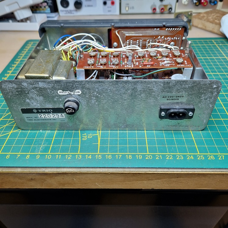
I removed both of these and added an IEC C14 connection:
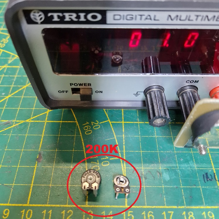
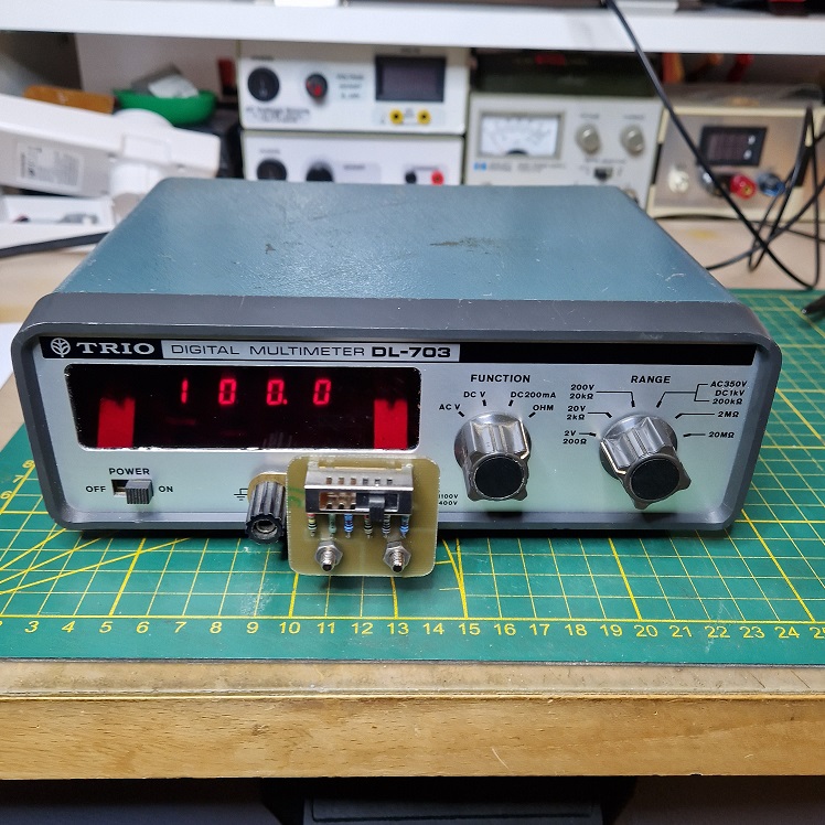
When I wanted to adjust the meter I discovered that the potentiometer for the 2V/20V range was defective, perhaps my own fault because with the shaver like main socket it worked fine. It concerns the metal potentiometer here in the photo:
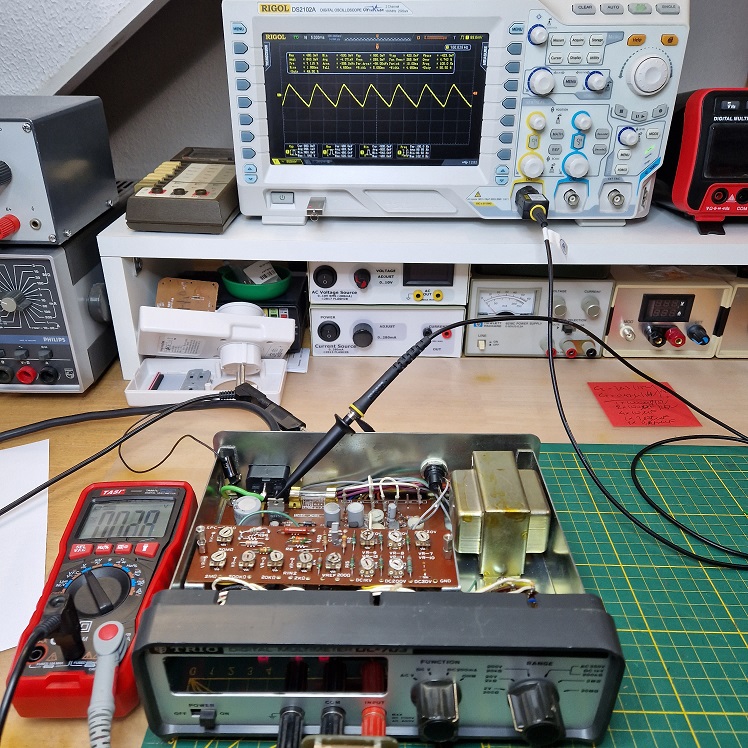
Another problem with this meter was the issue of unstable "back and forth" of the last digit. To tackle this, I first measured the 3 power supplies of the meter.
The power supply consists of +12V / -12V and +5V. The symmetrical +/- 12V uses two uA723s where the positive power rail is also the reference for the +5V. All electrolytic capacitors in this circuit are gray and from the Hitachi brand.
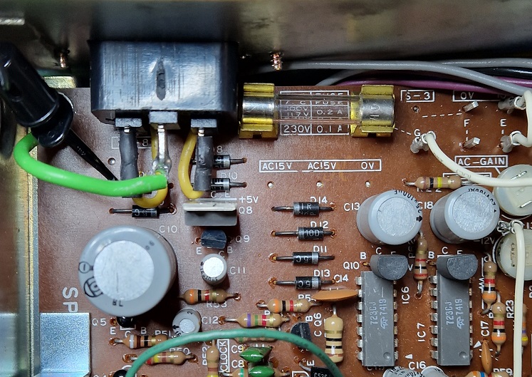
I measured the capacitance, ESR and DC leakage of all electrolytic capacitors. Basically they weren't that bad. The worst was C12, especially the DC leakage was 4x as high as its brothers. Because the meter is from around 1974, I replaced them all with Matsushita (Panasonic) units with the same capacity but 10V higher voltage. All parts in this meter are assembled by hand with bent connections, so it took a while before I had everything out and measuring all capacitance, ESR and DC leakage.
After this, the resistance measurement was re calibrated and the repair was successful, no more running back and forth of the last digit.
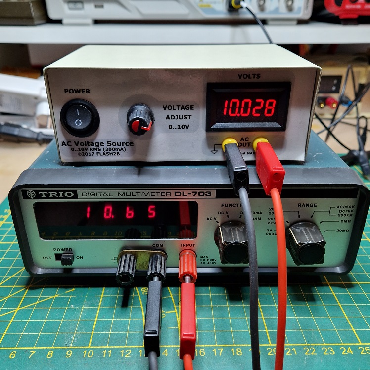
Finally, while waiting for a replacement potentiometer for the DC V range, I checked the AC V. This is especially higher at the end of the range, so from 0-9V it runs well and then it starts to deviate. I have experienced that before with my Metrix MX707A , so it is due to adjustment or an expired capacitor in the AC/DC converter.
There is still some work to be done, but we are moving in the right direction

Is there someone that has the Service Manual of this piece of kit in PDF ? That would really be useful for me.


