Author Topic: Replacement Knobs, Feet and Fittings for Test Equipment  (Read 531619 times)

0 Members and 1 Guest are viewing this topic.

Offline Jay_Diddy_B

  • Super Contributor
  • ***
  • Posts: 2765
  • Country: ca
Re: Replacement Knobs, Feet and Fittings for Test Equipment
« Reply #200 on: October 19, 2020, 08:06:29 pm »
Hi,

I am going to share the files for a pair covers for the Sorensen DCS series power supply. They will probably also fit the Xantrex XKW power supplies.

Input Cover


With no cover.


With the 3D printed cover. Printed in PETG.

Output Cover


Make sure that your power supply has the anchor points shown in the photo.


Cover installed on a unit:


I have attached a zipfile containing the STL files.

Regards,
Jay_Diddy_B

* sorensen.zip (53.26 kB - downloaded 322 times.)
 

Offline Jay_Diddy_B

  • Super Contributor
  • ***
  • Posts: 2765
  • Country: ca
Re: Replacement Knobs, Feet and Fittings for Test Equipment
« Reply #201 on: October 20, 2020, 12:11:42 am »
Hi group,

I am going to share the STL files for some feet for the Keithley 2001 DMM. These parts will probably fit other Keithley products.

I did not have an original, so I went on eBay looking for good photographs:


I then designed the replacement parts in Fusion 360:


3D Printing

PETG at 40% density was used for the hard plastic part.

TPU at 80% density was used for the rubber part and the front foot.


The rear feet are attached with 6-32 x 0.25" panhead screws.

I have attached a zipfile with the STL files.

Regards,
Jay_Diddy_B

* keithley 2001.zip (155.9 kB - downloaded 352 times.)
« Last Edit: October 20, 2020, 12:13:44 am by Jay_Diddy_B »
 

Offline uski

  • Frequent Contributor
  • **
  • Posts: 296
  • Country: us
Re: Replacement Knobs, Feet and Fittings for Test Equipment
« Reply #202 on: November 07, 2020, 04:13:46 am »
A long time ago I made a power button cap for my Tektronix TDS2024 oscilloscope :
https://www.thingiverse.com/thing:1426499
 

Offline nuno

  • Frequent Contributor
  • **
  • Posts: 606
  • Country: pt
Re: Replacement Knobs, Feet and Fittings for Test Equipment
« Reply #203 on: November 29, 2020, 03:51:36 pm »
I made these oscilloscope tip covers for my Rigol probes, I don't know if that's the name, I just call it that.

When I needed to probe tight places and assembled a cover, it usually made my life more difficult because the standard ones make the probe diameter larger and I always ended up bumping into something or not fitting the place, so I stopped using them. And they're also easy to loose, of course :D . Then I designed this slicker one. What do you think? The one in attach is for Rigol RP2200 probes (DS1104Z, probably the others too).

They're a bit tricky to print (at least for me), but doable. Depends on your slicer. This is designed to use the spiral mode, and I print it at 0.12mm Z step with a 0.4mm nozzle. In some slicers it helps to put the number of bottom and top layers to zero.

Here, with more info and design files: https://www.thingiverse.com/thing:4669269 . They are parametric, so you just need OpenSCAD and change some measurements in a file to fit your probes; I can help with that if needed.

« Last Edit: November 30, 2020, 02:07:24 am by nuno »
 
The following users thanked this post: tautech, mnementh

Offline mnementh

  • Super Contributor
  • ***
  • Posts: 17541
  • Country: us
  • *Hiding in the Dwagon-Cave*
Re: Replacement Knobs, Feet and Fittings for Test Equipment
« Reply #204 on: December 30, 2020, 09:13:43 pm »
         

I recently received a UTG962E Arb as a Christmas present from my wife; I got it because it is designed to fit in that space under a scope's chin when it sits up on the bail. Unfortunately, the bail on my 54645A has angle settings which are pretty much exactly wrong to produce that wedge-shaped space; and putting the Arb behind the bail makes it a PITA to use.  |O

So, I designed and printed a wedge base to get just the right angle, while opening up all that space under the beast.

This wedge raises the 54645A up 90mm at a point just behind the front feet of the scope; I put rubber feet underneath which add another 5mm. It does not block any airflow out of the 'scope; in fact, it directs the scope's air exhaust right towards the vented back of the UTG962E to keep air moving through. :-+

The nice thing, aside from the fact it keeps the UTG962E tucked neatly out of the way yet the front clear for use... is I actually gain almost 6 inches of clear space in front of the scope on top of my cart due to not having the bail jutting out.  :-+

This base should work with all 546xx family scopes and any that have the same 11.5" x 8.5" / 297mm x 214mm rectangular pattern with 28mm x 28mm feet; for comparison against other models, the space from front edge of the wedge to front edge of foot pocket is 159mm, and the top surface footprint is 207mm x 300mm, while bottom footprint is 196mm x 300mm. Foot pockets are 29mm x 29mm x 11mm deep.

I've attached the .stl files as a zip; my print settings were: CR6-SE printer, BLACK PLA, Default Temps of 200°C/60°C, 0.28mm LH, 20% Infill Cubic pattern, 1.2mm walls, 0.8mm top/bottom, Brim adhesion, Only on Outside, 2mm wide, with Brim Distance at 0.2mm to make Brim easy to separate. EDIT: Supports ONLY on LEFT side, as RIGHT side has no overhangs. Top/bottom pattern set to Concentric for appearance.

Cura estimates ~13 hours print time per half, with ~155grams filament at a cost of $3-4.50 per half at $20-30/2.2Kg roll, so ~$6-9 total cost and ~26 total hours.


Enjoy,

mnem
« Last Edit: January 01, 2021, 04:32:46 am by mnementh »
alt-codes work here:  alt-0128 = €  alt-156 = £  alt-0216 = Ø  alt-225 = ß  alt-230 = µ  alt-234 = Ω  alt-236 = ∞  alt-248 = °
 

Offline SilverSolder

  • Super Contributor
  • ***
  • Posts: 6126
  • Country: 00
Re: Replacement Knobs, Feet and Fittings for Test Equipment
« Reply #205 on: December 30, 2020, 11:59:00 pm »
I'm beginning to warm up to 3d printing....  :D
 

Offline mnementh

  • Super Contributor
  • ***
  • Posts: 17541
  • Country: us
  • *Hiding in the Dwagon-Cave*
Re: Replacement Knobs, Feet and Fittings for Test Equipment
« Reply #206 on: December 31, 2020, 04:13:35 pm »
« Last Edit: January 01, 2021, 04:36:08 am by mnementh »
alt-codes work here:  alt-0128 = €  alt-156 = £  alt-0216 = Ø  alt-225 = ß  alt-230 = µ  alt-234 = Ω  alt-236 = ∞  alt-248 = °
 
The following users thanked this post: SilverSolder

Offline mnementh

  • Super Contributor
  • ***
  • Posts: 17541
  • Country: us
  • *Hiding in the Dwagon-Cave*
Re: Replacement Knobs, Feet and Fittings for Test Equipment
« Reply #207 on: January 16, 2021, 05:23:54 pm »
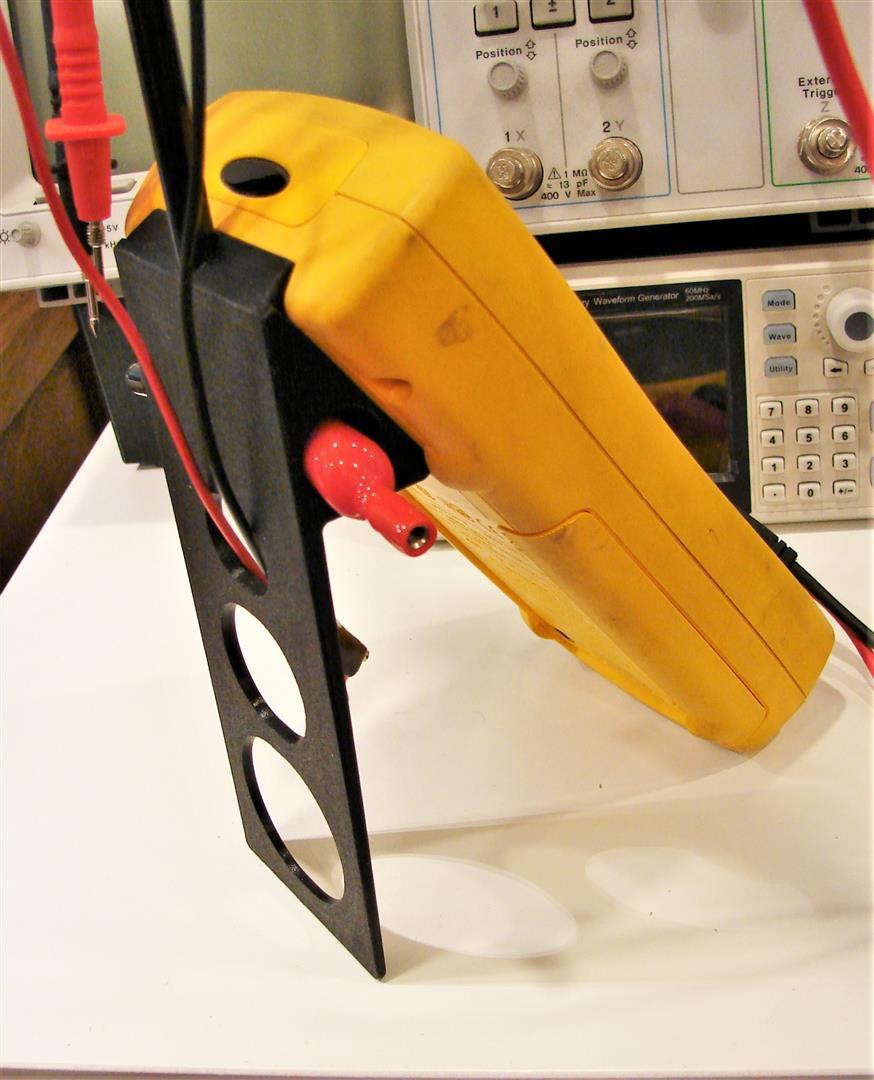
Bench Stand for FLUKE 189 & 87/IV DMM


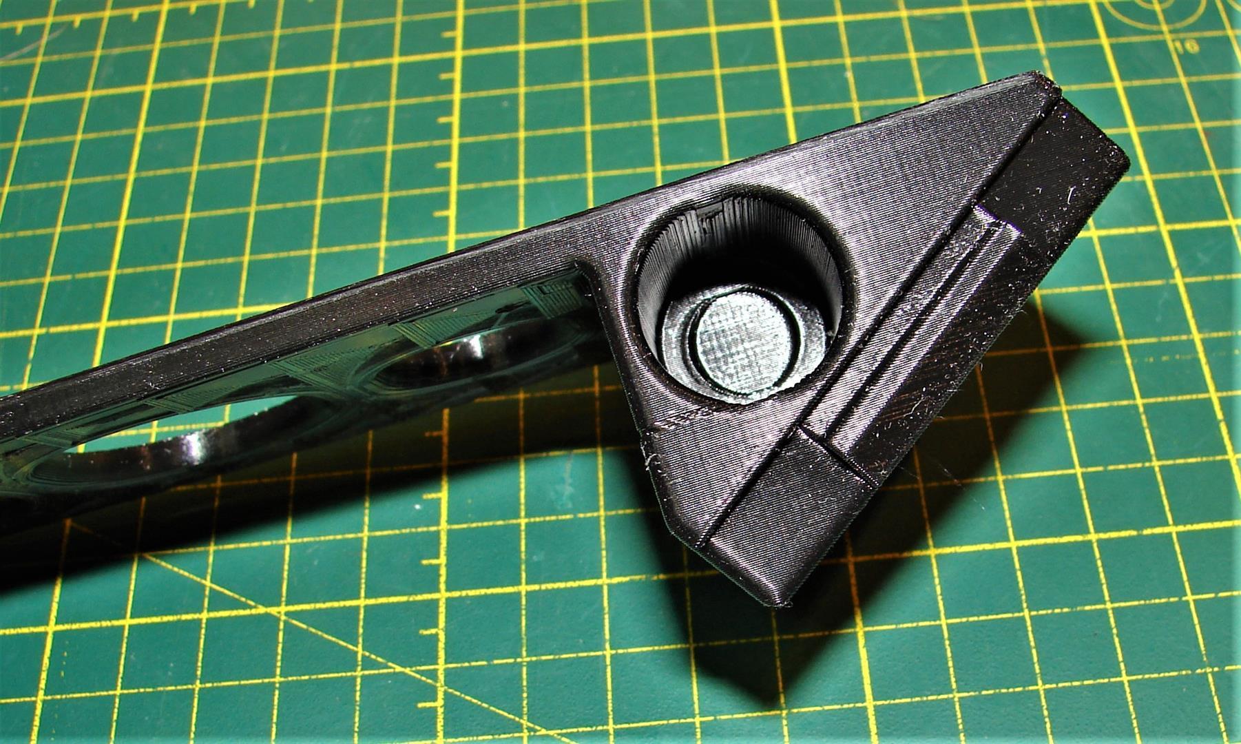
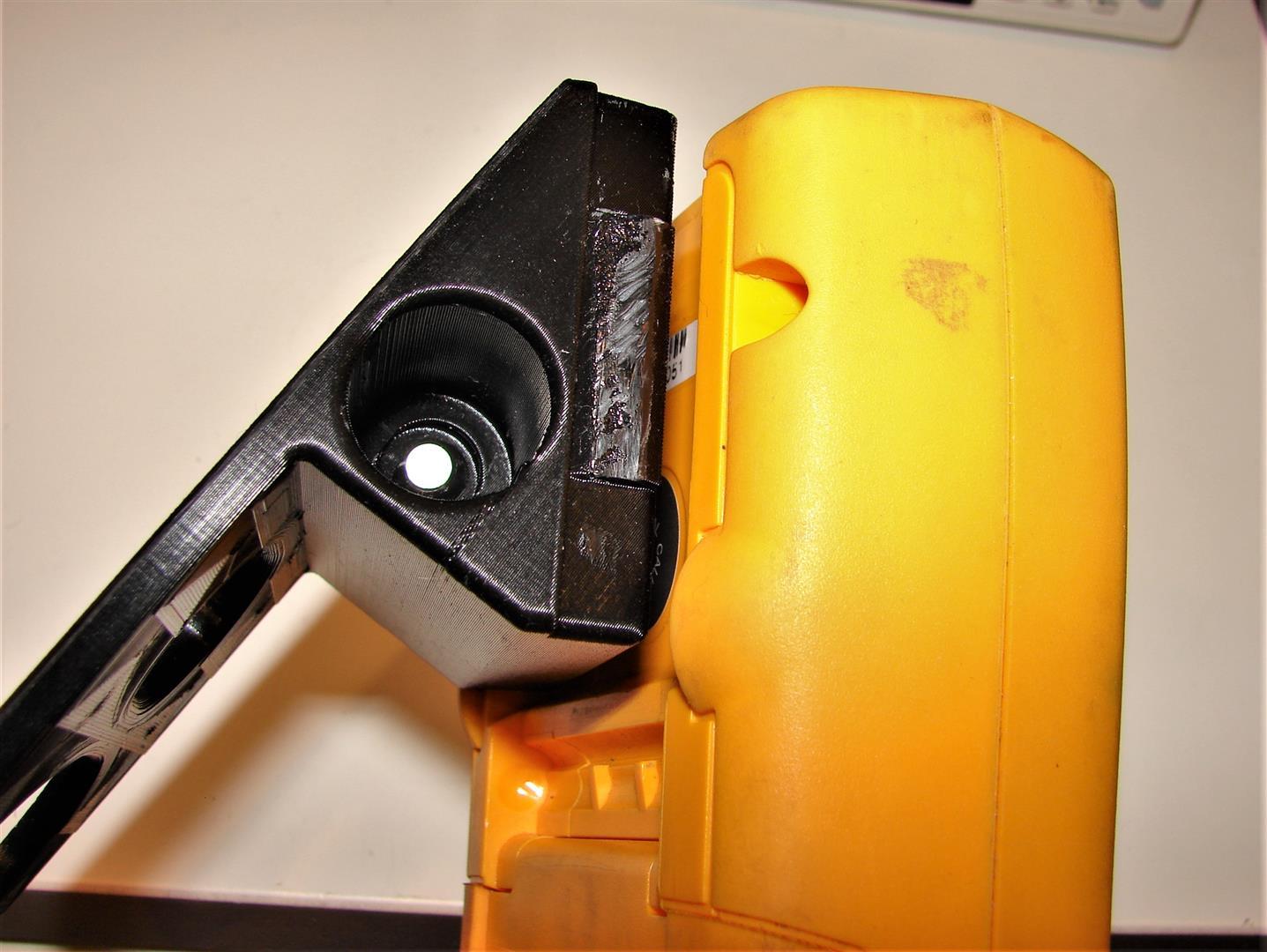
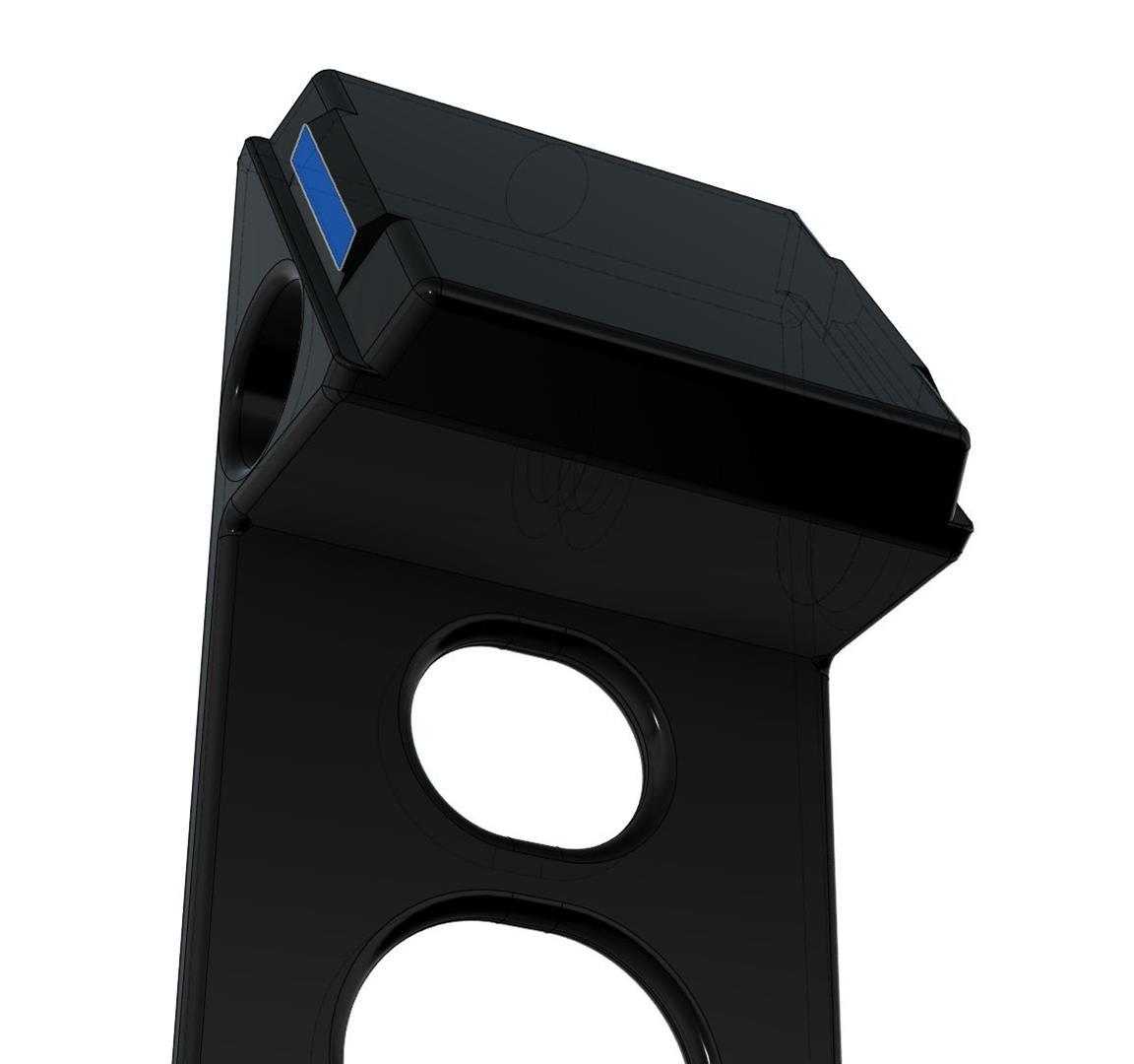
This is what I've been doodling around with the last couple days... a properly rigid bench-use stand for my Fluke 189 that incorporates a lead holder. This unit snaps in place of the molded rubber test-lead keeper usually found on the back of these meters; it does not interfere with the original flip-out stand in any way. The idea was to have all my most-used accessories and the leads all tidy and right there when I need them. The design scope was:
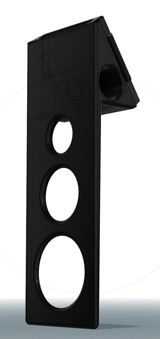
   

A) Easy to print: Stand base is designed to print flat on its back, while both parts make heavy use of gradual tapers and curves; this means they print well without supports as long as you have Bridging Mode enabled and rotate the part to present areas that need bridging best to the fan. Any stringing caused by printing without supports tends to be much easier to clean up than the mess left behind by supports.


B) Easy to use: Once assembled, entire unit snaps in/out easily. The oversized back disc serves a purpose; it makes it easy to loop the wires over the groove one-handed and the optional wire across the middle allows similar one-handed clipping of favorite alligator leads up to 24" long as well as IC grabbit leads. Reliefs in the stand serve to keep loose alligator wires from causing trouble, and magnets in the pockets keep the screw-on alligators in place.


2) Minimal BOM: Aside from ~150g filament, all you need is (2) 10mm neodymium disc magnets and some ~8mm round dowel, tube or rod approx 300mm long. I found this closet widget which can yield 5 segments of straight tubing 285mm long for $2 at the local Dollarama. Magnets are glued in with epoxy or CA gel.


Same epoxy, CA gel or hot-glue can be used on the tube sockets at final assembly; the entire assembly lies flat which makes it easy to get it all perfectly square. Hot-glue has added benefit of being easy to undo; just hit the tube with hot-air gun and it'll come right apart.


C) Easy assembly: The stand base snaps into the Hanger accessory slots on back of the Fluke 189; one side has a deep tab that fits precisely, while the other side that snaps in is designed a little too thick so you have to sand/trim with a knife to get it to snap in just right.


E) Better with Upgrades: 1mm holes at 90° angle for the wire are part of the model; tin-plated steel mechanic's wire or the center core from a scrap of CATV R6 works well here. Push through the hole, pull tight then melt-embed in the plastic with a hot soldering iron. Cut wire flush with nippers, then pot hole from iron with epoxy. If you can't be arsed, 1mm hole is easy to ignore. If you just want the base, I've got multiple versions with no hole in the top.


EDIT: A quick Update to add a generic adapter for the IR Module

A fellow member asked aboot a mount for the Fluke IR Module... and in researching, I found that there were a lot of folks in here who'd rolled their own IR Datalogging adapters as well as looking for the bracket for the OEM IR module. To help out, I've designed this little adapter to fit the Rev2.2 Stand with hole for 8mm shaft. It provides a 30mm x 50mm flat plate you can attach your OEM IR Module or your DIY module to with double-faced foam mounting tape or adhesive-backed Velcro strips.

It is bundled together with the correct version of the meter stand in the 2nd zip file below. :-+

For strength, both parts should be printed 0.20-0.16LH, laying flat on largest flat surface (back of Meter Stand, front face of IR Adapter bracket), and with infill set to yield a grid pattern with 1-1.5mm spacing. Both parts will print well with no supports.


Cheers!

mnem
 :-DMM
« Last Edit: October 14, 2021, 09:25:02 pm by mnementh »
alt-codes work here:  alt-0128 = €  alt-156 = £  alt-0216 = Ø  alt-225 = ß  alt-230 = µ  alt-234 = Ω  alt-236 = ∞  alt-248 = °
 
The following users thanked this post: SilverSolder

Online TERRA Operative

  • Super Contributor
  • ***
  • Posts: 3084
  • Country: jp
  • Voider of warranties
    • Near Far Media Youtube
Re: Replacement Knobs, Feet and Fittings for Test Equipment
« Reply #208 on: January 17, 2021, 05:38:36 pm »
I drew up the rear foot to suit the 2445/2465 family of Tektronix scopes.
I haven't printed it yet, but it should be 99% accurate.

https://www.thingiverse.com/thing:4726857
Where does all this test equipment keep coming from?!?

https://www.youtube.com/NearFarMedia/
 
The following users thanked this post: mnementh

Offline mnementh

  • Super Contributor
  • ***
  • Posts: 17541
  • Country: us
  • *Hiding in the Dwagon-Cave*
Re: Replacement Knobs, Feet and Fittings for Test Equipment
« Reply #209 on: January 18, 2021, 01:52:40 am »
Noice! I'll probably actually print that one too, once I have my 2465s back from deep storage stateside. :-+

mnem
 :popcorn:
alt-codes work here:  alt-0128 = €  alt-156 = £  alt-0216 = Ø  alt-225 = ß  alt-230 = µ  alt-234 = Ω  alt-236 = ∞  alt-248 = °
 

Online TERRA Operative

  • Super Contributor
  • ***
  • Posts: 3084
  • Country: jp
  • Voider of warranties
    • Near Far Media Youtube
Re: Replacement Knobs, Feet and Fittings for Test Equipment
« Reply #210 on: January 19, 2021, 12:48:17 am »
I haven't tried it myself yet, let me know how you go! :)
Where does all this test equipment keep coming from?!?

https://www.youtube.com/NearFarMedia/
 

Offline CatalinaWOW

  • Super Contributor
  • ***
  • Posts: 5455
  • Country: us
Re: Replacement Knobs, Feet and Fittings for Test Equipment
« Reply #211 on: January 22, 2021, 09:25:59 pm »
Here is a battery compartment cover for an OK Electronics Model 402 Digital Thermometer.  One of my favorite tools.  The battery cover has been missing for years.  Battery covers are tricky to model, finicky on dimensions.  To get the tabs on the end right it is best to print this with the tabs pointing up, using an island for adhesion and full support.  Zip file contains FreeCAD model and .stl file ready to slice and print.
 

Offline mnementh

  • Super Contributor
  • ***
  • Posts: 17541
  • Country: us
  • *Hiding in the Dwagon-Cave*
Re: Replacement Knobs, Feet and Fittings for Test Equipment
« Reply #212 on: January 23, 2021, 09:14:33 pm »
         

Not exactly test equipment... but gear a great many of us have to deal with nonetheless. The Hitron CODA series is probably the single most popular DOCSIS3.1 MODEM/Gateway in service right now. Every ISP seems to be using them.

One of the big PITA issues is that they have a slight overheating problem; while designed for vertical implementation, they still have problems with dropouts that you can read about in oodles of media site threads. Any old 5-12V fan plugged into the USB port and aligned so it makes the air move across the thing even a little seems to resolve the issue; this is something I proved to myself in our last location.

Here, I needed to be able to stick the thing under my desk, but it simply is too tall. So, a cheap 120mm PC case fan and some feet were in order. The 120mm/12V case fan running on 5V draws minuscule current, and runs slow enough to be absolutely silent, while still actively pulling plenty of air through the unit.

The fan bracket is a slight friction fit on the pegs, which are offset to match the pattern of the vents in the body of the Hitron CODA. The pegs on the feet snap in positively; feet raise the unit ~18mm off the floor.

Both parts print well without supports as long as you have Bridging Mode enabled and rotate the part to present areas that need bridging best to the fan. Any stringing caused by printing without supports tends to be much easier to clean up than the mess left behind by supports.
Feet take ~13min/2grams each to print with infill set to 2mm grid. Fan bracket takes ~58 minutes/8 grams at same settings.

Note that turning this unit on its side tends to refocus the WiFi propagation pattern; it is best to locate this unit on an outer wall or corner with the original bottom (end with rubber feet) facing the wall.

mnem
 :-/O
alt-codes work here:  alt-0128 = €  alt-156 = £  alt-0216 = Ø  alt-225 = ß  alt-230 = µ  alt-234 = Ω  alt-236 = ∞  alt-248 = °
 

Offline cowasaki

  • Frequent Contributor
  • **
  • Posts: 605
  • Country: gb
Re: Replacement Knobs, Feet and Fittings for Test Equipment
« Reply #213 on: January 30, 2021, 12:03:17 am »
Just in case anyone wants to hang their Peak Atlas testers on the wall I have created 3D printable wall brackets. 

The brackets are in twos or fours but they go together so you could print 3x twos for six in a line or a two and a four for 2x3 etc

Uploaded to thinyverse for storage.

https://www.thingiverse.com/thing:4741886
 
The following users thanked this post: mnementh

Offline aargee

  • Frequent Contributor
  • **
  • Posts: 877
  • Country: au
Re: Replacement Knobs, Feet and Fittings for Test Equipment
« Reply #214 on: February 01, 2021, 05:32:15 am »
Hello all,

(Posted in the main Test Equipment group but also posted here as it fits this thread too. Thanks for the suggestion, Tautech)

I've modified my HOPI meter to make it a bit safer (in my opinion) and give it a three-pin AUs GPO socket. I used a 3D-Printed adaptor block and a Jaycar panel-mount socket, I also removed the speaker terminals.

Details here http://www.engineershed.com/
3D Model here https://www.thingiverse.com/thing:4744289

- Rob (yes, absolutely crap at keeping an up-to-date website.  :D )
Not easy, not hard, just need to be incentivised.
 
The following users thanked this post: tautech, mnementh

Offline quadtech

  • Regular Contributor
  • *
  • Posts: 69
  • Country: in
Re: Replacement Knobs, Feet and Fittings for Test Equipment
« Reply #215 on: February 26, 2021, 10:53:56 am »
Tek 465 Scope - AC/DC Input Coupling - does anyone know what the conical rubber top is called,
and any source for the replacement? TIA!
like the one here -


Offline dl6lr

  • Frequent Contributor
  • **
  • Posts: 459
  • Country: de
Re: Replacement Knobs, Feet and Fittings for Test Equipment
« Reply #216 on: February 26, 2021, 01:25:49 pm »
Tek 465 Scope - AC/DC Input Coupling - does anyone know what the conical rubber top is called,
and any source for the replacement? TIA!

This may fit: https://www.thingiverse.com/thing:4776292
« Last Edit: November 24, 2021, 08:29:34 pm by dl6lr »
 
The following users thanked this post: quadtech

Offline dl6lr

  • Frequent Contributor
  • **
  • Posts: 459
  • Country: de
Re: Replacement Knobs, Feet and Fittings for Test Equipment
« Reply #217 on: February 26, 2021, 01:38:52 pm »
Tektronix YT-1S chart recorder
 printer knob.

https://www.thingiverse.com/thing:4776301

« Last Edit: November 24, 2021, 09:25:54 pm by dl6lr »
 

Offline Fuzzy Star

  • Contributor
  • Posts: 30
  • Country: 00
Re: Replacement Knobs, Feet and Fittings for Test Equipment
« Reply #218 on: March 02, 2021, 02:39:46 pm »
Tek 465 Scope - AC/DC Input Coupling - does anyone know what the conical rubber top is called,
and any source for the replacement? TIA!

This may fit: https://www.thingiverse.com/thing:4776292
Quadtech, if that is a blade switch, like dl6lr posted you can search "blade switch knob" and find knobs like these:
https://www.aliexpress.com/item/32795643601.html
https://www.aliexpress.com/item/32793502264.html
 

Offline Michael YYZ

  • Regular Contributor
  • *
  • Posts: 72
  • Country: ca
Front Case and Rotary Selector for Wavetek 2020?
« Reply #219 on: March 09, 2021, 09:59:26 pm »
Would anyone have any idea about where I could get a front case + selector button for a Wavetek 2020 DMM? Not only the plastic travel limiters are broken - and the button rotates 360 degrees freely - but also the centre sleeve of the button has cracked and the button slides off the meter easily.


It’s a rather rare meter, but one that I’ve been very fond of. It still works, despite the issues, but I’d be very happy if I could fix / replace the case and the rotary button.


Thank you.
 

Offline Michael YYZ

  • Regular Contributor
  • *
  • Posts: 72
  • Country: ca
Re: Replacement Knobs, Feet and Fittings for Test Equipment
« Reply #220 on: March 09, 2021, 10:31:51 pm »
My DMM (the one in the middle). ❤️
 

Offline CatalinaWOW

  • Super Contributor
  • ***
  • Posts: 5455
  • Country: us
Re: Replacement Knobs, Feet and Fittings for Test Equipment
« Reply #221 on: March 10, 2021, 04:50:58 pm »
Safety cover for Tektronix 576 curve tracer.  This cover keeps your fingers away from dangerous voltages, and triggers the interlock allowing those voltages to be applied.  The original is clear, apparently so that you can see the warm glow of an overheated transistor, but the opaque printed version keeps light out of packages that allow semi-conductors to be photosensitive.  If you miss the opportunity of watching transistors melt you can always bodge in a plexiglass window.

ZIP file is model in FreeCAD format and stl format.  Some may want to modify for taller cover.
« Last Edit: March 10, 2021, 05:02:31 pm by CatalinaWOW »
 
The following users thanked this post: NF6X, richnormand

Offline ch_scr

  • Frequent Contributor
  • **
  • Posts: 872
  • Country: de
Re: Replacement Knobs, Feet and Fittings for Test Equipment
« Reply #222 on: March 27, 2021, 06:48:45 am »
Front breakouts for Keithley 2600 SMU. Flat or with feet, mirrored or same layout L/R. Uses "Hirschmann PK 10 A" binding posts.
More info, files & discussion: https://www.eevblog.com/forum/testgear/keithley-2600-front-breakout/
 

Offline TheDefpom

  • Frequent Contributor
  • **
  • Posts: 763
  • Country: nz
  • YouTuber Nerd - I Fix Stuff
    • The Defpom's Channel
Re: Replacement Knobs, Feet and Fittings for Test Equipment
« Reply #223 on: April 16, 2021, 01:00:28 am »
Switch shaft extension as used in the Fluke 341A and Fluke 343A DC Calibrators, and also in some other products too I think.

https://www.thingiverse.com/thing:4824180
« Last Edit: April 16, 2021, 01:04:27 am by TheDefpom »
Cheers Scott

Check out my Electronics Repair, Mailbag, or Review Videos at https://www.youtube.com/TheDefpom
 
The following users thanked this post: xrunner

Offline belzrebuth

  • Frequent Contributor
  • **
  • Posts: 487
  • Country: gr
Re: Replacement Knobs, Feet and Fittings for Test Equipment
« Reply #224 on: June 18, 2021, 11:53:20 am »
Has anyone found a suitable replacement for the switch caps used in HP 3312A?
I see those broken all the time and sure enough two of mine are also broken as well.
I have similar switch caps in my 5316A counter and I'm sure they should fit other HP instruments of this era..
They look like in the photo below.

HP part numbers are :

WHITE         : 0370-0604
LIGHT GREY : 0370-0668
GREY           : 0370-2781
« Last Edit: June 18, 2021, 11:58:03 am by belzrebuth »


Share me

Digg  Facebook  SlashDot  Delicious  Technorati  Twitter  Google  Yahoo
Smf