I cannot justify spending $400 for a new proper DSO, or $250 and up for a proper used DSO. I briefly considered a used analog scope, but I have used analog scopes before and I wanted something different. It is either a one of these or do without. Rather than doing without, I decided to get the Hantek 6022BE. I spend just under $77 for it.
(I was waiting for it went you posted this comment)
I have neither the skill nor the equipment to do a proper review. When I was deciding, I so wished to see what the 6022BE could do and how the rendered waveform would look like. Since you are deciding, I will share with you what I can and cannot do with it. And I will also share a few observations. I hope the info will help you decide.
First,
this is not a scope you grow with. This is a scope you learn the limitation of and live within. You will outgrow this one if you stay in EE. This is a “try-out” scope. If you are in EE for real and for the distance, a proper scope will serve you better.
Here is what I tried that the scope can/cannot do (1st weekend of ownership, so I have not yet discovered all the can/cannot):1. The build-in reference waveform - with all the noise include. The noise is around +-10mV, not too bad except when you are dealing with 50mV. I saw one “unboxing” video and the other guy had the noise too. So I was expecting that and it did not caused disappointment.
Attachment 1: The build in reference waveform with both channels. 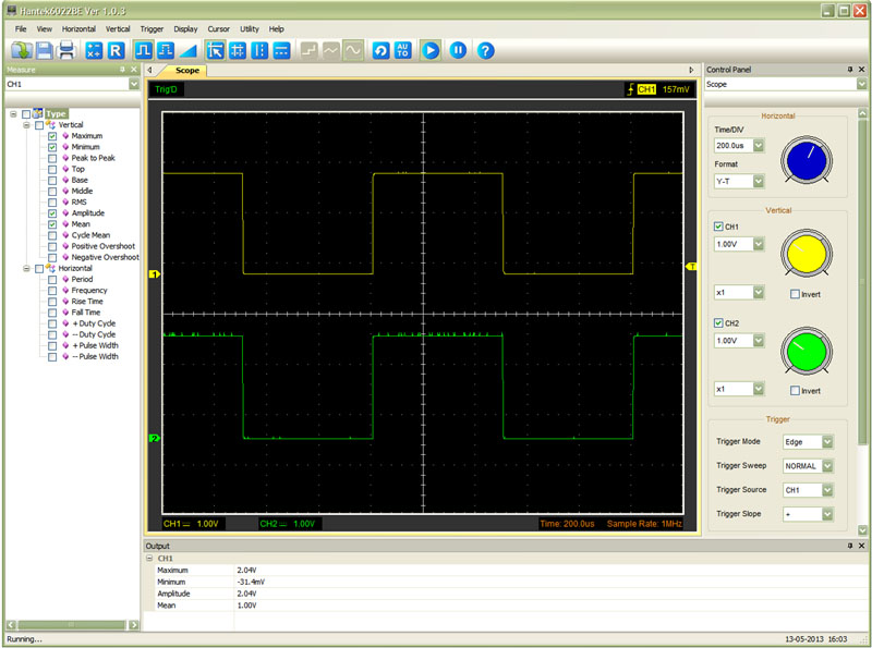 2. Triangle ~57khz
 - I made a home made booster using the MC34063 a few weeks back. I was still twiddling with it to learn. By the MC34063 datasheet, I should have a triangular wave on the timing pin when properly timed. I know it is working so something should be there. Below is how the (approx) 57khz triangle looks on the 6022BE. The frequency matched the UT-61E reading almost to-the-dot. I also used the scope to find the inductor with least ripples in my limited inventory of four unlabeled ones. That was successful in a sense (I found the one with least ripples but least ripples does not equate to best). So had that been the goal, it could have been done.
Attachment 2: The triangular wave at around 57khz 3. Just for kicks, I added an OpAmp
 to trigger compare the wave to a fix voltage just to see how it behaves. I had expected more of a square wave but it is not nearly square. (I will get into rise time later. I don’t think it is rounded because of a slow rise time for the 6022BE, I think it is rounded because of other things.)
Attachment 3: The triangular wave (yellow) fed into an OpAmp (green), and using the math to have CH1 - CH2 (blue). The math can do + - x / and FFT. 4,5,6. Inductor resonance
 - With my few inductors without label, I wanted to know approximately what they are. I connected up a tank circuit to measure for that. These pictures below are measuring a marked
400uH inductor paired with a 10uF capacitor for illustration. Both are old removed components from a power supply.
Attachment 4: The ring (not the movie…)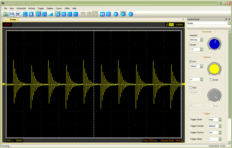 Attachment 5: I can zoom in
 some but the reading can be more accurate yet. Measuring the frequency at this magnification,
the 400uH calculates to be 370uH. (Still within expected margin, but doming more illustrating of the scope.)
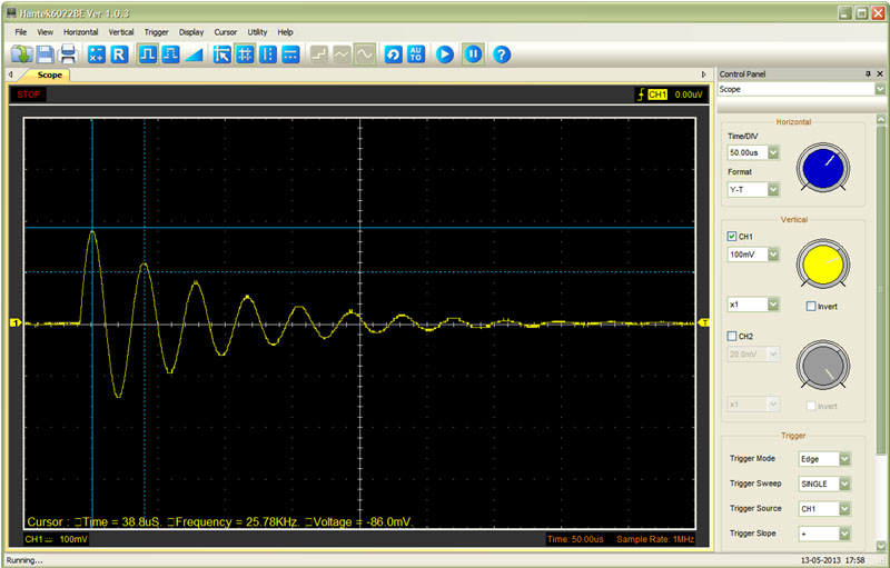 Attachment 6: Zoom in more.
 (Showing you 6022BE’s smaller division) With smaller t/div the measured frequency is more accurate.
This time, the 400uH is calculated to be 385uH.
 7. See the LM2577’s output pin:
 The LM2577 is set to max at just around 23-27Volt.
Attachment 7: LM2577’s output pin.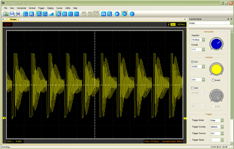 8. A closer look into just one cycle of the LM2577’s output.
 Looking at the square (rectangular) part, it is just about twice as wide as a 1MHz square wave, so a 1MHz square wave should show reasonably well.
Attachment: one cycle of the LM2577’s output 9. Since the OpAmp output does not look square
, and the 6022BE spec has rise time=10%-90%!!! Since they would not even put in a number, I decided to do a few more things (illustrated below) to get an idea how fast the 6022BE
rise time is using the LM2577’s output pin:Attachment – note, I purposely put the cursor one dot below the waveform so you can see the yellow waveform. This is a vertical+horizontal cursor. The machine supports 3 types of cursor: Vertical, horizontal, or H+V.
(Note also: when zooming in, the display shows the capture rate IF you run it at that time/div BUT NOT the actual time/div when the data was captured.) With the close zoom, I saw that there was only 1 single data point during the rise! Including the data point before and after, the whole rise took 3 data points only. So an even closer inspection was done later. When including the before/after data point, the measurement (141ns) is an “upper bound”.
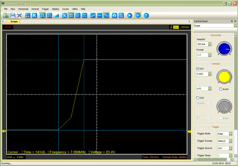 10. For a better measurement of the rise time
, I switch to the highest capture rate. Here is one place where the 6022BE’s spec could be misleading.
At 48MegaSamples/Second (2uSec/div or less per division) it captures merely 1060 data points or about 21uSec of data. It is hard to find a good way to trigger it to catch the rise when the wave period is longer than the capture duration. This one happens to have a good undershoot at the end of each period, so I triggered on that point. Otherwise, I would have needed to press the “RUN” button (with single shot) again and again to try to catch the right 21uSec. More on data points in “other notes” below.
Using 48MS/S, the upper bound for the rise took 80ns with 5 samples taken: before+3 during rise+after. With a
rise time of 80ns, I am optimistic it appears it may be able to show 1MHz-2Mhz square wave reasonably well.
 Other notes:1. Lots of noise
 making triggering difficult (around +- 3 to 10mv). I think the noise makes the scope triggered early (or late) by a sample point or two. At around 100KHz, the waveform jitters a lot (left-right by 1/10 of a division). It was discerning at first. After a while, I got use to it and can get a good sense of how the waveform looks. Of course, I used pause or do the single-shot for measurement.
2. The print is worthless. The yellow waveform cannot be seen against the white background. Screen print is good.
3. Did I say noise?4. The accuracy is not so great. It is suppose to be 3%, but at certain voltage the error is a lot worst. (I used my 4 months old UT-61E as reference. I expect it to still be in-spec.) The readings were consistently high in my case. It got better at times (warm up?) but I don’t have a handle on that yet. Calibration doesn’t help.
Error percentage table for 1x probe and 10x probe, 1st column is the 10x probe
10x probe 1x probe
5v 3.0% >4.6%
4.6v (reading tops out at 4.71v for 1x probe)
4.5v 2.7% 4.6%
4v 2.0% 4.2%
3.5v 4% 3.7%
3v 2.3% 4.6%
2.5v 0.4% 4%
2.0v 1.5% 5%
1.5v 0.0% 2.7%
5. Data points – At 2uSec or below, it capture at
48MS/S for merely 1016 data points. At the next setting (5uSec per division) it captures 130048 data points at 16MS/S. The data point keeps increasing as sample rate decreases but not linearly. At 200ms/division it samples at 500KS/S and collects 1,047,552 data points so the spec’s 1 Mega points is correct. You can save the data, but there is no time stamp for data points.
6. No delay trigger, DC coupling only7. Did I tell you lots of noise? (It is bad but not drop dead. After I got used to it and I mentally tune it out, I was able to spot the “ring resonance” to measure inductance at 50mV scale even while the noise is 10mV.) I do wish it is cleaner…
So, to wrap up, so far, I am satisfied with it at under $77 USD. If I continue to dig back into EE a year from now, (and/or business condition changes), I would feel more justified to spend more on a scope. Right now, it is that or nothing and I am pleased I got that.
Good luck with your decision.
Rick
(EDIT: inserted the image in-line
EDIT2: Grammatical)