Author Topic: Power supply for home lab - do I really need a R&S?  (Read 5682 times)

markus_jlrb, gburdzin, asmi, Messtechniker, blackdog, iv3wjr, Furna and 16 Guests are viewing this topic.

Offline rf-messkopf

  • Regular Contributor
  • *
  • Posts: 167
  • Country: de
  • Mario H.
    • Homepage
Re: Power supply for home lab - do I really need a R&S?
« Reply #50 on: Yesterday at 05:18:53 pm »
That's totally unacceptable behavior from any supply, it's a disaster in the waiting for just about any sensitive electronics use we can think of.

I don't disagree with that statement but this behavior is quite common for a number of supplies from reputable manufacturers.

I just tested the supplies I currently have on the bench. All set to 8 V, 10 mA, loaded with 50 ohms. The attached pictures show the output voltage when the load is connected to the supply.

HMP4040-E3646A.png: green trace: R&S HMP4040, white trace: Agilent E3646A.
6632B.png: Agilent 6632B, with rear panel "Fast/Normal Operation" switch set to "normal" (notice the time scaling).

The Agilent 6632B hangs at 8 V for about 150 ms.
 

Offline ArdWar

  • Frequent Contributor
  • **
  • Posts: 679
  • Country: sc
Re: Power supply for home lab - do I really need a R&S?
« Reply #51 on: Yesterday at 05:34:58 pm »
Keithley 2281 :o
2390643-0

Keithley 2281 with 100V/s slew limit
2390647-1

R&S NGP800  :o :o (Note the different vertical scale)
2390651-2

Keithley 2461 (I mean, I'll burn their HQ if it didn't work properly)
2390655-3


Online mahi

  • Regular Contributor
  • *
  • Posts: 100
  • Country: 00
Re: Power supply for home lab - do I really need a R&S?
« Reply #52 on: Yesterday at 05:36:17 pm »
Rohde & Schwarz HMP4040 (pre-facelift).

Tested at 8V and 20V with 10 mA current limit in a 50 ohm load. Even at 32V the output looks the same as the 20V test.
« Last Edit: Yesterday at 07:02:59 pm by mahi »
 

Offline 2N3055

  • Super Contributor
  • ***
  • Posts: 7197
  • Country: hr
Re: Power supply for home lab - do I really need a R&S?
« Reply #53 on: Yesterday at 05:43:55 pm »

I don't disagree with that statement but this behavior is quite common for a number of supplies from reputable manufacturers.


Maybe it is time we start reconsidering difference between good reputation and legends and lore..
And assign brand value according to actual results and not "reputable brand" urban legends...
 
The following users thanked this post: egonotto, thm_w, tautech, rf-messkopf, moerm

Offline rf-messkopf

  • Regular Contributor
  • *
  • Posts: 167
  • Country: de
  • Mario H.
    • Homepage
Re: Power supply for home lab - do I really need a R&S?
« Reply #54 on: Yesterday at 05:56:24 pm »

I don't disagree with that statement but this behavior is quite common for a number of supplies from reputable manufacturers.


Maybe it is time we start reconsidering difference between good reputation and legends and lore..
And assign brand value according to actual results and not "reputable brand" urban legends...

True. Attached: same test with a 20 year old homemade supply, completely analog.  :)

Note: My tests show the load being connected to the supply, with the output already on.
 
The following users thanked this post: 2N3055

Offline thm_w

  • Super Contributor
  • ***
  • Posts: 7078
  • Country: ca
  • Non-expert
Re: Power supply for home lab - do I really need a R&S?
« Reply #55 on: Yesterday at 06:01:47 pm »
I think the control loop is in software though. I have an Agilent 66311B which has the same 'problem' (delayed current limit). If the current limit is done in an analog circuit, then I don't see how you can screw up a power supply circuit that bad. OTOH, it could be done to deal with circuits which have a rush-in current which otherwise wouldn't start up properly. Some DC-DC converter modules are prone to not starting when the current limit is set too low. But I can't see this as a good point on a general purpose lab PSU though.

With the 66311B "Mobile Communications DC Source" you could make the argument its not a general purpose PSU, so there will be trade-offs to optimize it for high speed response. I would argue a general purpose PSU should prioritize safety and stability over speed.

Here is an old R&S DC source PSU (ngmo), same issue but much faster response:
Profile -> Modify profile -> Look and Layout ->  Don't show users' signatures
 

Online mhsprang

  • Contributor
  • Posts: 29
  • Country: nl
Re: Power supply for home lab - do I really need a R&S?
« Reply #56 on: Yesterday at 06:44:05 pm »
That's totally unacceptable behavior from any supply, it's a disaster in the waiting for just about any sensitive electronics use we can think of.

I don't disagree with that statement but this behavior is quite common for a number of supplies from reputable manufacturers.

I just tested the supplies I currently have on the bench. All set to 8 V, 10 mA, loaded with 50 ohms. The attached pictures show the output voltage when the load is connected to the supply.

HMP4040-E3646A.png: green trace: R&S HMP4040, white trace: Agilent E3646A.
6632B.png: Agilent 6632B, with rear panel "Fast/Normal Operation" switch set to "normal" (notice the time scaling).

The Agilent 6632B hangs at 8 V for about 150 ms.
If the output is enabled before you connect the load, you will obviously see a spike due to the capacitor on the output of the PSU. The idea is that you connect the load first, then enable the output. That is what I have been doing. And in that case, I think no overshoot should be tolerated.
 
The following users thanked this post: nctnico, thm_w, Kean, mawyatt

Offline rf-messkopf

  • Regular Contributor
  • *
  • Posts: 167
  • Country: de
  • Mario H.
    • Homepage
Re: Power supply for home lab - do I really need a R&S?
« Reply #57 on: Yesterday at 06:56:46 pm »
If the output is enabled before you connect the load, you will obviously see a spike due to the capacitor on the output of the PSU. The idea is that you connect the load first, then enable the output. That is what I have been doing. And in that case, I think no overshoot should be tolerated.

Okay, I thought you are after the transition from voltage to current regulation. Attached see the test with the output being switched on (green trace: HMP4040, white trace: Agilent E3646A), load is 50 ohms again.
« Last Edit: Yesterday at 07:10:30 pm by rf-messkopf »
 

Online mhsprang

  • Contributor
  • Posts: 29
  • Country: nl
Re: Power supply for home lab - do I really need a R&S?
« Reply #58 on: Yesterday at 07:43:02 pm »
Here are the results from the power supplies I have at home. The Delta is a pure analog supply, the TTi is at least digitally controlled, has a keyboard and all, but I don't know of the control loop is analog or digital. The Tenma is also digitally controlled but cheap: €99. Setup is 8V, 10 mA in 50 Ohm. Load connected, then outputs enabled. Two screen shots each with different time bases, to see short term spikes and "long term" stabilisation of the set current.
 

Online mawyatt

  • Super Contributor
  • ***
  • Posts: 3808
  • Country: us
Re: Power supply for home lab - do I really need a R&S?
« Reply #59 on: Yesterday at 08:00:51 pm »
That's totally unacceptable behavior from any supply, it's a disaster in the waiting for just about any sensitive electronics use we can think of.

I don't disagree with that statement but this behavior is quite common for a number of supplies from reputable manufacturers.

I just tested the supplies I currently have on the bench. All set to 8 V, 10 mA, loaded with 50 ohms. The attached pictures show the output voltage when the load is connected to the supply.

HMP4040-E3646A.png: green trace: R&S HMP4040, white trace: Agilent E3646A.
6632B.png: Agilent 6632B, with rear panel "Fast/Normal Operation" switch set to "normal" (notice the time scaling).

The Agilent 6632B hangs at 8 V for about 150 ms.
If the output is enabled before you connect the load, you will obviously see a spike due to the capacitor on the output of the PSU. The idea is that you connect the load first, then enable the output. That is what I have been doing. And in that case, I think no overshoot should be tolerated.

That's what we've shown (with Blue LED as load), and agree on acceptable overshoot!!

Best
« Last Edit: Yesterday at 08:14:14 pm by mawyatt »
Curiosity killed the cat, also depleted my wallet!
~Wyatt Labs by Mike~
 

Online nctnico

  • Super Contributor
  • ***
  • Posts: 27836
  • Country: nl
    • NCT Developments
Re: Power supply for home lab - do I really need a R&S?
« Reply #60 on: Yesterday at 08:11:48 pm »
Just to add another data point: The Keysight E36313A behaves OK. Set to 20V, 8mA with a 47 Ohm resistor attached.


I had to use 500mV/div other wise the scope wouldn't trigger.
There are small lies, big lies and then there is what is on the screen of your oscilloscope.
 

Offline rf-messkopf

  • Regular Contributor
  • *
  • Posts: 167
  • Country: de
  • Mario H.
    • Homepage
Re: Power supply for home lab - do I really need a R&S?
« Reply #61 on: Yesterday at 08:12:26 pm »
That's what we've shown, and agree on acceptable overshoot!!

Sure, but still the settling time when transiting from voltage to current regulation varies among different supplies and can be rather long. The Agilent 6632B takes over 150 ms with a 50 ohms load, for example, as I show in the post above. I find this rather disappointing. That will fry a LED instantly when connected to the supply when in CV mode with the output on. I should test that supply with the rear panel switch set to "fast".
 

Offline 2N3055

  • Super Contributor
  • ***
  • Posts: 7197
  • Country: hr
Re: Power supply for home lab - do I really need a R&S?
« Reply #62 on: Yesterday at 08:51:24 pm »
That's what we've shown, and agree on acceptable overshoot!!

Sure, but still the settling time when transiting from voltage to current regulation varies among different supplies and can be rather long. The Agilent 6632B takes over 150 ms with a 50 ohms load, for example, as I show in the post above. I find this rather disappointing. That will fry a LED instantly when connected to the supply when in CV mode with the output on. I should test that supply with the rear panel switch set to "fast".

Well, that is mostly because of large capacitors on the output. To make it worse, internal impedance of capacitors is in milliohms...

Current sources for testing sensitive devices usually have shorted outputs when you are connecting DUT, and you remove short to ramp up voltage/current in controlled manner. Current sources also can have voltage limiters, where you can set max voltage, and if current source is unloaded, limiters work like parallel regulators. Basically adjustable zener in paralel to DUT.

Actually, that kind of device could be easily constructed and added as additional device in parallel to PSU output to "clamp" any misbehaviour....
 
The following users thanked this post: egonotto, rf-messkopf

Offline rf-messkopf

  • Regular Contributor
  • *
  • Posts: 167
  • Country: de
  • Mario H.
    • Homepage
Re: Power supply for home lab - do I really need a R&S?
« Reply #63 on: Yesterday at 09:04:56 pm »
Well, that is mostly because of large capacitors on the output. To make it worse, internal impedance of capacitors is in milliohms...

The output voltage curve doesn't look like a discharging capacitor, though. Rather, the supply sits there for milliseconds before the voltage ramps down, same with the R&S, but much shorter. That's particularly unfortunate with the 6632B since it is a two-quadrant supply and can sink current up to the maximum rated output current.

But I don't mean to hijack this thread as it is about a different topic.
« Last Edit: Yesterday at 09:18:45 pm by rf-messkopf »
 
The following users thanked this post: egonotto, thm_w, 2N3055

Online blackdog

  • Frequent Contributor
  • **
  • Posts: 752
  • Country: nl
  • Please stop pushing bullshit...
Re: Power supply for home lab - do I really need a R&S?
« Reply #64 on: Yesterday at 09:11:19 pm »
Hi,

As promised some measurements I made on LAB power supplies I own that have an enable key that are here on the test bench.

Almost all measurements were made under the same conditions.
Of the Agilent and the Siglent LAB power supply I have made additional measurements with in the case of the Siglent a higher current of 35ma and in the case of the Agilent I have increased the voltage and the current setting, this to investigate to what extent their behavior depends on the current setting.
For convenience I have placed a picture of the LAB power supply under test in each picture.

Basic settings
Voltage setting 8V
Current 10mA

The power supply is switched on with the enable button.
Two measurements per LAB power supply channel were taken using the single shot method on the scoop.
This to get a better understanding of the power-on behavior of the LAB power supply.
A Pk-Pk mA measurement is visible at the bottom left in yellow.

Let's start with the Rigol DP832.
First channel-1, but... that is R&S behavior  :-DD

.

Let's zoom in on the horror.

.

And now to channel-2 which, by the way, has the same characteristics and virtually the same peak current of about 25mA.

.

And zoomed in again, that looks distinctly different from channel-1.

.

Channel three of the Rigol can only deliver a maximum of 5.3V and the current is again set at 10mA.

.

Hir is clearly visible that this channel behaves well, the peak current remains below 10mA.

.

The following pictures are of a single channel Siglent LAB power supply and that is the SPD1305.
This Siglent is not so kind to its load at this small current, 36mA peak current.

.

Lets ZOOM in.
It takes 30mSec for the current to drop to double the value of 20mA, you can do better Siglent!

.

I wanted to see if this Siglent Power Supply shows a different behavior at larger currents, below is a measurement at 35mA.
At this 35mA, the behavior is much better.

.

Only a small overshoot is visible and the abberations just after power-up are not significant.

.

Now shall we go watch some more horror?  ;)
WTF 130ms more than 160mA!

.

One positive is that the pulse is completely clean.

.

Now let's see if at 200mA the behavior is below, I increased the voltage to 12V.
There is comparatively less overshoot now, but, but.... 500msec long!

.

Now to the last one LAB power supply that behaves better and that is the GW Instek GPP4323.
This Power Supply has four channels and channel one and two are the same so I am only showing channel one.
Look R&S, Agilens and Rigol, this is how it should be.

.

Immediately after turning on, a small abberation is visible but that is not important, the peak current remains below the set 10mA.

.

This is a measurement performed on channel-4.
Looks good.

.

There are some abberations in the beginning, but the peak current remains below the set value.

.

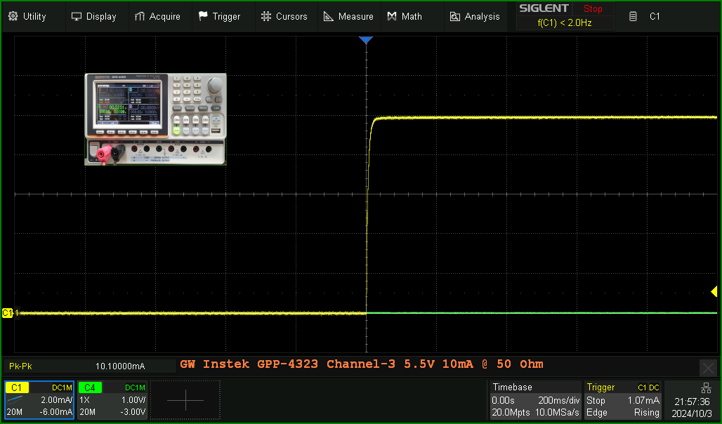
And now for the final measurements, still the GW Instek Power Supply and now channel-3.
This channel can only deliver a maximum of 5.5V and that is what the measurements below were made with.

.

A little hickup at the beginning, but well below the set peak current, no problemo, are you watching R&S, this is how it should be *grin*.

.

From these measurements, it is clear to see that the “ current loop” of the GW Instek is a lot faster than the other Power Supply's I measured.

Many of the Power Supply manufacturers make the current loop comparatively slow, then the power supply as a whole is easier to keep “stable”, but everything has its price, which is also visible in my measurements an from others in this topic.

I hope to see more measurements from you!

Greetings,
Bram
Necessity is not an established fact, but an interpretation.
 
The following users thanked this post: nctnico

Offline thm_w

  • Super Contributor
  • ***
  • Posts: 7078
  • Country: ca
  • Non-expert
Re: Power supply for home lab - do I really need a R&S?
« Reply #65 on: Yesterday at 09:26:39 pm »
Hi,

As promised some measurements I made on LAB power supplies I own that have an enable key that are here on the test bench.

Its good that you measured current, probably should standardize on that.
Peak of the first one was 25mA, R&S was 120mA, so not nearly as bad, IMO, but still not good.
« Last Edit: Yesterday at 09:39:15 pm by thm_w »
Profile -> Modify profile -> Look and Layout ->  Don't show users' signatures
 

Online blackdog

  • Frequent Contributor
  • **
  • Posts: 752
  • Country: nl
  • Please stop pushing bullshit...
Re: Power supply for home lab - do I really need a R&S?
« Reply #66 on: Yesterday at 09:38:52 pm »
Hi thm_w ,  :D

I measured the voltage across a 50 Ohm resistor and set the scope channel to indicate the current value.

I think it is all about not exceeding the set current and then it is more obvious that you indicate the current value on the scope image.

That an LED can handle 2 or 4 times the maximum current for time “X” is not so important.
Every LAB power supply is used for all kinds of other applications.

My moral from almost 60 years of experience.
I always test an LED with a series resistor.
If I ever want to push some power into a battery, I always do it via a series diode.

I don't like “fast”, I like to be careful and make sure that I don't break the d.u.t. I connect to a LAB power supply.

Kind regards,
Bram
Necessity is not an established fact, but an interpretation.
 
The following users thanked this post: thm_w, 2N3055

Offline thm_w

  • Super Contributor
  • ***
  • Posts: 7078
  • Country: ca
  • Non-expert
Re: Power supply for home lab - do I really need a R&S?
« Reply #67 on: Yesterday at 09:40:25 pm »
I think it is all about not exceeding the set current and then it is more obvious that you indicate the current value on the scope image

Agreed, updated my post.
Profile -> Modify profile -> Look and Layout ->  Don't show users' signatures
 

Online Martin72

  • Super Contributor
  • ***
  • Posts: 6700
  • Country: de
  • Testfield Technician
Re: Power supply for home lab - do I really need a R&S?
« Reply #68 on: Yesterday at 10:32:45 pm »
Fast current control is a good thing for sensitive components if you want to connect them directly to the power supply.
However, there are situations where this is rather counterproductive.
Certain DC/DC converter circuits have an inrush current that can easily be many times the normal input current.
If this is not taken into account when switching on, it can, at best, lead to non-functioning without side effects, but in some cases it can lead to permanent current flow, causing the circuit to “hang”.
As always, the dose makes the poison.
However, I also prefer series resistors for LEDs, it's just in my nature... ;)
"Comparison is the end of happiness and the beginning of dissatisfaction."
(Kierkegaard)
Siglent SDS800X HD Deep Review
 
The following users thanked this post: pdenisowski

Offline rf-messkopf

  • Regular Contributor
  • *
  • Posts: 167
  • Country: de
  • Mario H.
    • Homepage
Re: Power supply for home lab - do I really need a R&S?
« Reply #69 on: Today at 12:16:41 am »
Fast current control is a good thing for sensitive components if you want to connect them directly to the power supply.
However, there are situations where this is rather counterproductive.

The delayed switchover from CV to CC mode, where the supply sits there for a few milliseconds before an exponential ramp down is seen (as expected for a capacitor discharged through a resistor), might actually be implemented on purpose. This delay might also be responsible for the overshoot that is seen when the output is switched on with the enable button with a load connected.

The current control loop itself seems to be much faster. Attached is the result of the following experiment: Supply (R&S HMP4040) is set to 8 V, 150 mA, output on, and loaded with a 50 ohms resistor (i.e., it is in CC mode with 7.5 V at the output). Then an additional 4.7 ohms resistor is switched in parallel to the 50 ohms (i.e., output voltage should jump down to 0.64 V). The transition takes about 1.7 ms (from 90% to 10%) and looks exponential as expected for a cap discharged through a resistor, with no obvious delay before the exponential decrease.

Maybe R&S can comment on this behavior.

If it is intentional, it would be nice if the user had control over it, though.

Edit: Repeated the same measurement, but with the 4.7 ohms resistor switched in by a MOSFET in order to demonstrate that there is no appreciable delay between switching and supply response. Lower trace is the gate drive pulse.
« Last Edit: Today at 01:12:16 am by rf-messkopf »
 
The following users thanked this post: pdenisowski

Online KungFuJosh

  • Super Contributor
  • ***
  • Posts: 2595
  • Country: us
  • TEAS is real.
Re: Power supply for home lab - do I really need a R&S?
« Reply #70 on: Today at 12:58:58 am »
As promised some measurements I made on LAB power supplies I own that have an enable key that are here on the test bench.

What probe were you using to do these measurements?

Thanks,
Josh
"Right now I’m having amnesia and déjà vu at the same time. I think I’ve forgotten this before." - Steven Wright
 

Offline pdenisowski

  • Frequent Contributor
  • **
  • Posts: 909
  • Country: us
  • Product Management Engineer, Rohde & Schwarz
    • Test and Measurement Fundamentals Playlist on the R&S YouTube channel
Re: Power supply for home lab - do I really need a R&S?
« Reply #71 on: Today at 01:28:11 am »
Thanks to everyone for all the analysis and comparison.  As I mentioned above, I've already communicated all of this to the power supply team in Munich and we are investigating.  It would also be very helpful if the OP could contact our technical support about this and/or contact their R&S sales representative as well.

One (potentially ignorant) question:  has the behavior of the NGE (or other manufacturers' supplies) been outside of its published specifications? 

I've seen lots of test results for lots of supplies (and again, many thanks for those), but I haven't seen any comparisons of experimental results to published specifications.  That would have been one of the first things I checked - is a given supply "in spec"? 

My apologies if that's a dumb question.
Test and Measurement Fundamentals video series on the Rohde & Schwarz YouTube channel:  https://www.youtube.com/playlist?list=PLKxVoO5jUTlvsVtDcqrVn0ybqBVlLj2z8
 
The following users thanked this post: egonotto

Offline moerm

  • Regular Contributor
  • *
  • Posts: 54
  • Country: aq
  • pragmatic realist
Re: Power supply for home lab - do I really need a R&S?
« Reply #72 on: Today at 02:11:00 am »

I don't disagree with that statement but this behavior is quite common for a number of supplies from reputable manufacturers.


Maybe it is time we start reconsidering difference between good reputation and legends and lore..
And assign brand value according to actual results and not "reputable brand" urban legends...

I logged in specifically and just to thank you for that.

But being logged in anyway ...

Fast current control is a good thing for sensitive components if you want to connect them directly to the power supply.
However, there are situations where this is rather counterproductive.
Certain DC/DC converter circuits have an inrush current that can easily be many times the normal input current.
If this is not taken into account when switching on, it can, at best, lead to non-functioning without side effects, but in some cases it can lead to permanent current flow, causing the circuit to “hang”.
As always, the dose makes the poison.
However, I also prefer series resistors for LEDs, it's just in my nature... ;)

I get it but let me play a bit Cassandra ...

With a *linear* *lab* PSU my main concern is potentially sensible stuff (being powered). You are right, there are exceptions and corner cases in almost everything which leads to a need for deciding for priorities (mine I just told). Besides switchers tend to care little about the quality of input power, many circuits however *do* care.

Some of my - almost all self designed and built - PSUs do have a "don't limit (DUT) inrush current for 3 or 10 ms (selectable) with a 0 ms option (~no tolerance, strictly stick to the set current limit)" feature and most of them have a separate "emergency brake" set to double the set current limit (max the highest output current of that supply). Reason: a supply should be "generous and tolerant" but not to the point of getting damaged itself.

What I've seen here (thanks guys!) would have been, had I known it (I didn't) yet another reason to  design and build my PSUs myself rather than buying "well known brands". I'm not really surprised though that "famous A-tier brands" sell what I call crap; maybe my wording is a bit harsh but "A tier brand" quality certainly is not what I see here (modulo one "B-tier" brand).

Whatever, thanks for all the data (and nice images *g).
« Last Edit: Today at 02:14:23 am by moerm »
VxWorks - Yes! Linux - meh. Windows - Thanks no, definitely.
 
The following users thanked this post: mhsprang

Offline ArdWar

  • Frequent Contributor
  • **
  • Posts: 679
  • Country: sc
Re: Power supply for home lab - do I really need a R&S?
« Reply #73 on: Today at 03:31:26 am »
One (potentially ignorant) question:  has the behavior of the NGE (or other manufacturers' supplies) been outside of its published specifications? 

Personally I'm not exactly sure since it is tricky to figure out which specifications override what, and whether those interrelated specifications should be interpreted strictly ("any" exceed) or loosely ("all" exceed).
For example, if we take my NGP800 load current regulation spec strictly (< 0.01% + 5mA) then my peak result of 160mA inrush at startup is well beyond the allowable spec range of 10mA * 0.01% + 5mA, which basically allows for 15.001mA max inrush.
The inrush duration is also well beyond "Load recovery time" spec of 400µs, so can't use that either to handwave.
NGP800 does not specify CV-to-CC transition time. Is this the "get out of jail free" card? :o

Fuse delay time *may* allow this, but that's protection function while the discussed performance should be regulation function. And sure enough if I set the fuse to protect close to the setpoint (20mA) it did indeed trip on itself during startup. Job well done there.
 
The following users thanked this post: pdenisowski, mhsprang

Online mhsprang

  • Contributor
  • Posts: 29
  • Country: nl
Re: Power supply for home lab - do I really need a R&S?
« Reply #74 on: Today at 07:53:54 am »
Fast current control is a good thing for sensitive components if you want to connect them directly to the power supply.
However, there are situations where this is rather counterproductive.
Certain DC/DC converter circuits have an inrush current that can easily be many times the normal input current.
If this is not taken into account when switching on, it can, at best, lead to non-functioning without side effects, but in some cases it can lead to permanent current flow, causing the circuit to “hang”.
As always, the dose makes the poison.
However, I also prefer series resistors for LEDs, it's just in my nature... ;)

Agreed on inrush currents, but those will be obvious if you switch on the power.

But that is not the point of all of this. If we set a voltage on our PSU, we expect that PSU to output that voltage, no more. Similarly, if we set a current, we expect that PSU to output that current, no more. If a manufacturer specifies that a set current may be +/-5% + 5 mA, I do not expect the output current to be 14 times higher than that. And if the design shows transients at enabling the output, I want to see that beforehand in the datasheet and not after the purchase on my bench.


Share me

Digg  Facebook  SlashDot  Delicious  Technorati  Twitter  Google  Yahoo
Smf