Serious question: why do you test at 300MHz scope at 900MHz and 1GHz?
It is also important to know analog front end bandwidth.
Sorry this image txt is finnish language but main thing is perhaps clear.
Note that many times oscilloscopes nameplate BW is over image
fBW usually 1.3 - 1.8x when signal is directly connected to 50 ohm input with good impedance match. (combination BW, Probe + scope front is other case)
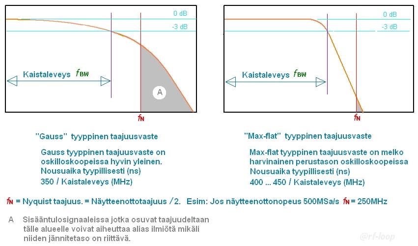
In image all what is in grey area (A) produce alias.
If want be sure that there is not high amount of aliasing then analog front end need filter out all frequency components what go over
fNyquistIn these images can not see how much high frequencies are attenuated, only can see that it can trig and produce sinewave image. But also, in these images signal do not go to
fNyquist what is in this case 1.25GHz. If this scope use not interleaved mode then samplerate maax is 1.25GSa/s and then
fNyquist is 625MHz.
Many cheap oscilloscopes have analog front end what go far over
fNyquist so that signal level is still high when reach
fNyquist. In these cases specially with signals what have high frequency components, example fast edges, measurements may be total false due to aliasing.
For serious use it is very good to know true analog front end frequency bandwidth and BW shape also up to least
fNyquist. Many times these "hackers" do not understand this at all or other reason is that just only do not care. Only what they understand (or want) is how much MHz and thinking that more is better. I have never seen "hacker" or modifier who make his equipment better so that they reduce BW and make BW shape more steep so that
fNyquist is enough attenuated.
But most important is: Know your tools. This may need many kind of tests before serious use.
If I can hope I like to see this R&S high class scope real analog front end BW shape from 0 to 1.2GHz.


