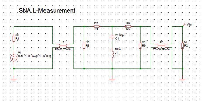
Unfortunately, I cannot answer that question either, but it reminds me on a test fixture I’ve built some 30 years ago in order to measure small inductors at appropriate frequencies, which happens to have a Pi structure.
It was intended to be used with a scalar network analyzer – in fact an SA with TG and out of my memory, it looked like this:

Basically a 20dB attenuator that helps to keep the port impedances reasonably constant and a reference capacitor that forms a series resonance circuit with the unknown inductor.
The following graph shows the result for 100nH, 1µH and 10µH:

With a reference capacitor of 25.33pF, resonances will occur at 10MHz for 10µH, 31.6MHz for 1µH and 100MHz for 100nH, which should match the usual frequency range for these inductor values, but can easily be adapted of course.
The quality of the inductor can be estimated by the max. attenuation at the series resonance frequency. 20dB additional attenuation (= 40dB total) means a series resistance of 18 ohms, likewise 40dB (60dB total) would indicate a series resistance of 1.8 ohms. From that it should be easy to calculate the Q of the inductor, provided that a high quality capacitor (maybe an air trimmer) is used and the quality of the resonance circuit is almost entirely determined by the inductor.