I noticed this in reading the user manual:
Although the dc source can operate in either mode, it is designed as a constant voltage source. This means that the unit turns on in constant voltage mode with the output voltage rising to its Vset value. There is no command for constant current operation. The only way to turn the unit on in constant current mode is by placing a short across the output and then enabling or turning the output on.
So I decided to do some captures of the turn on behaviour, which might be of interest here. All measurements are done with a 1X probe, and all done with the output enable switch. I don't think that will cause any measurement issues for these, but let me know if I'm wrong about that.
Let's start with unloaded 15V:
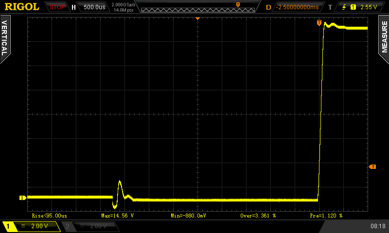
Hmm curious glitch there before the supply comes online. I wonder if it's related to the program voltage or load, and if it might be a problem powering very sensitive...stuff that can't handle a ~2.5Vpp 100us spike.
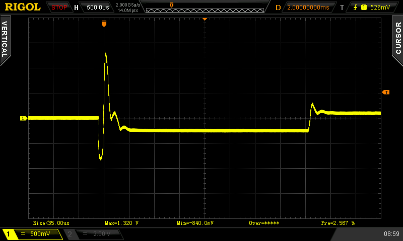
Nope, doesn't seem to be. Very similar with a 50R load and 100mV program voltage. Looks to be almost exactly 8ms before the main loop starts, during which time the output goes negative, and looks the same regardless of parameters or load (I assume subject to the supply's drive capability). It seems to be related to the output enable/disable switching, as it doesn't appear when going from 0V to 5V with the output enabled. The overshoot also seems to be much more prominent here compared to with a higher output voltage, though it's not quite constant.
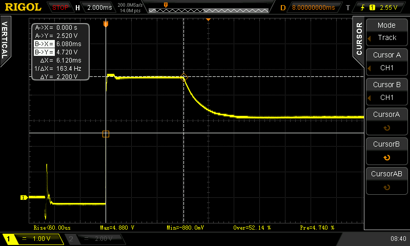
On to the 'start in constant current mode' tests. First I decided to test a capacitor directly hooked up to the supply, figuring this would be a challenge for the output amplifier. I selected a nice beefy 6800uF cap from the junk box and set the supply to 14V / 100mA:

So with this load, it looks like it takes 6-7ms for the current loop to kick in and regulate to a constant current. Not shown is charging, which looks nice and linear, and the switch back to CV mode after charging the cap also looks nice and clean, no hint of oscillation or ringing.
Next up is intended to simulate a high-power LED, as 4 1N4007 in series across the supply at 100mA and a 5V set point:
This one is very similar, as it takes 6ms for the current loop to kick in. Then we get what looks like a discharge curve down to the constant current. I guess this might be related to diode capacitance or maybe Vf changing as I goes down when we go into CC mode.
Finally the supply into a purely resistive 50R load, first in constant current configuration set for 100mA @ 14V:
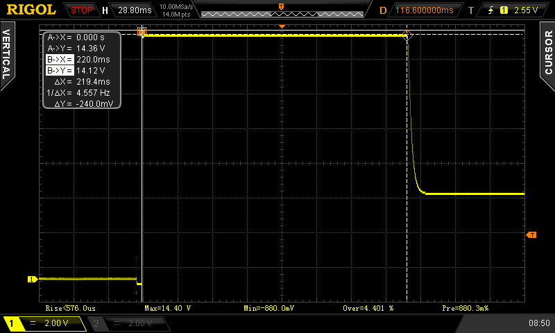
Wow it's really slow to kick into CC mode with a resistive load! 220ms. My hypothesis is that the loads above would appear as nearly a dead short to the supply, pulling enough current to hit the 'peak' current limiter, and then ending up in CC mode after that. With the resistor, 14V/50R is only 280mA, so it runs that way for a while before the regular loop notices.
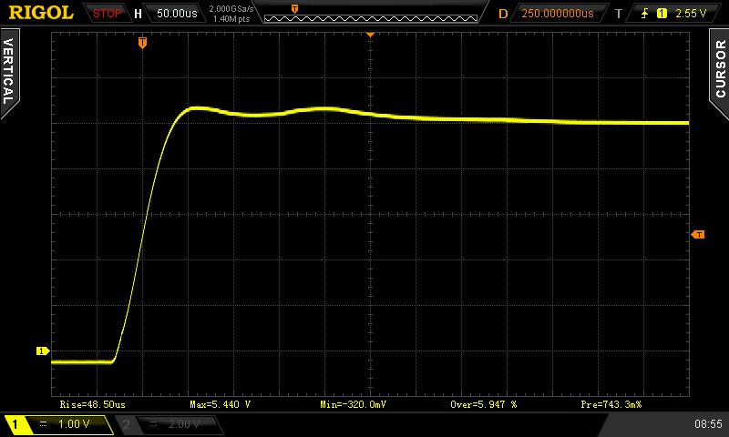
Finally a close up of CV mode into 50R, set to 5V/1A (the filenames are wrong on these, oops):
There are a couple more captures with my repair photos at
http://gotroot.ca/66311b/


