I gather everyone is probably tired of my blunders and repair attempts, but one final post...
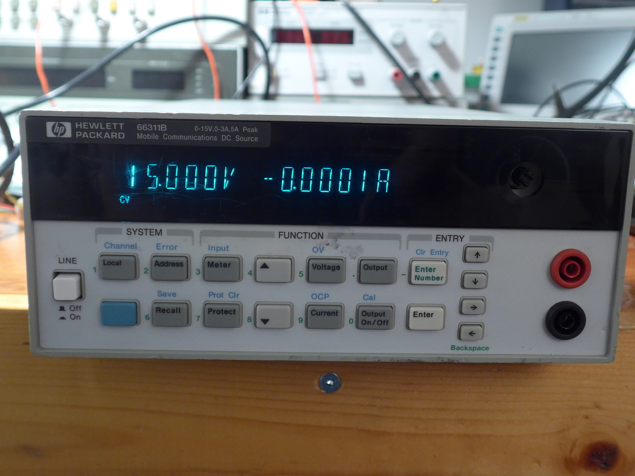
tl;dr after 6 hours of work tonight, my 66311B is fully operational and now has front-panel outputs!

The longer story is that the first thing to replace was the FFC cable, since I ripped that. Parlex 100R8-305B worked, though it's slightly shorter than the stock cable and more care was needed when re-attaching the front panel. Yet another thing I don't really like about the mechanical design of this box is that the flex has to go around a fairly sharp bend as it leaves the front panel, which created a kink at the stiffener and made it easy to break.
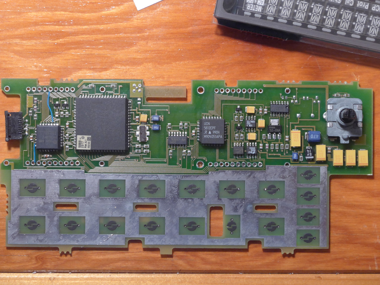
First things first, I replaced the obviously burnt UCN5812 with a new HV5812. Having never soldered PLCC by hand before, I didn't realize that this package is the spawn of Satan. After some fiddling around I got that installed. Added two bodge wires to the VFD pins in place of the pads I had damaged while removing the dead IC with a poor technique. A lot of hassle would have been saved if I had a hot air station...
At this point I also elected to replace the MAX773 DC-DC driver (which actually creates a 40V supply, not 12V as I had originally thought), because I thought it was also dead since there was no output on the regulated output pins. In hindsight the removed part may be functional, since the DC-DC in this design uses an external drive transistor and the internal outputs are not used.
These being the parts I suspected most strongly, I decided to give the board another try at this point. With the VFD sitting free and some pressure applied, I could now get all segments to light when powered on. There didn't seem to be any indication of activity on the display, just all segments lit. An hour or two of probing later I was pretty positive that the power supplies, drivers, and microcontroller were working properly. So being stupid, I decided to try soldering the VFD back on, just in case some pins weren't making contact and causing the all-segments issue. Of course this failed, and I had to desolder the thing again.
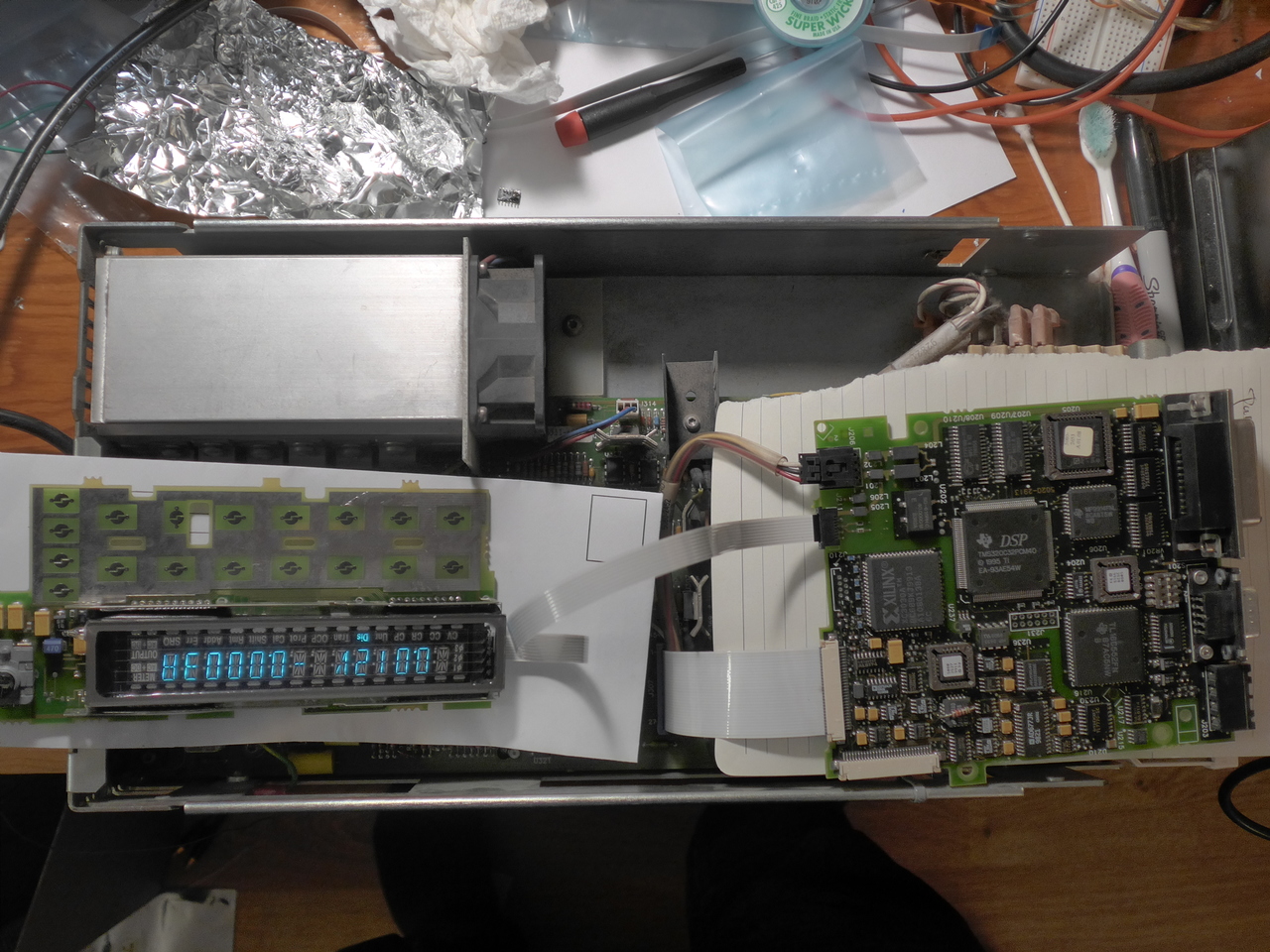
Now we're here:

I should have just replaced the pesky LM339 to begin with, I purchased one and it was cheap and easy insurance. The one on the board
seemed to be working, but I replaced it anyway. Immediately the VFD showed signs of life, though I wasn't able to get a proper display until it was soldered down. There wasn't much else left to do. During my previous probing I had already determined that I was pretty sure the transistors and other ICs on the board were working perfectly, so pretty much the last ditch was to power it up and cross my fingers. And lo and behold! It's alive!

So on to the front panel output mod. In my rummaging looking for replacement parts, I had found a pair of these Pomona 72913 jacks in red and black from a long abandoned project:

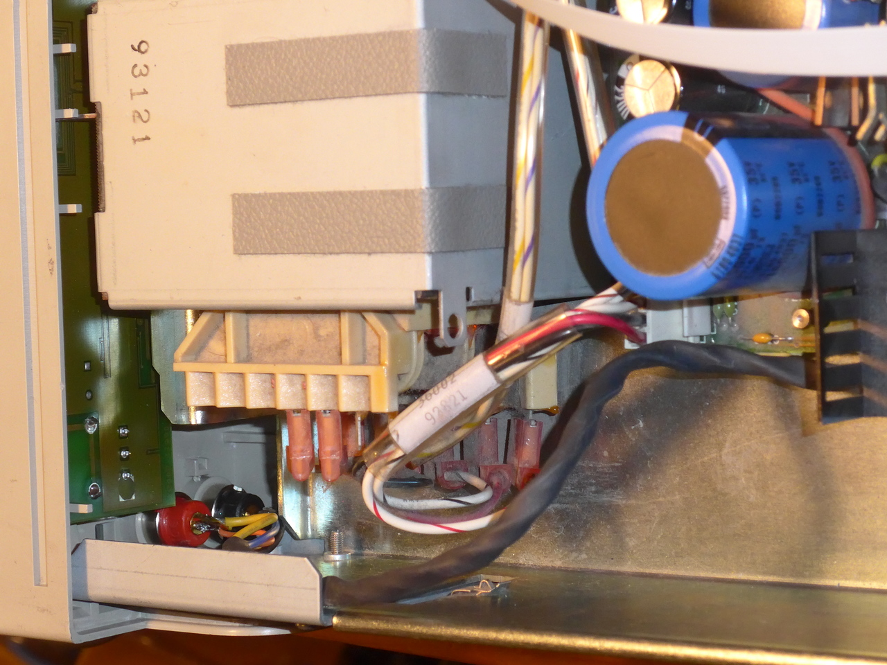
They were very close to fitting perfectly in the existing front panel cutouts. I did have to enlarge the holes by 1mm or so, but it was an easy fit. Somewhat unfortunate that they are 'safety' jacks, but I felt I would have a hard time mounting the traditional type due to the depth and size of the holes in the plastic. Plus I had them on hand. With the holes enlarged, they mounted easily. I chose to solder directly to the bottom pads of the rear output connector. My first whack at this had the wires interfering with one of the mounting standoffs, so I had to redo it to avoid that. My choice was to bring the 'remote' sense lines from the connector to the front panel and short them directly to the output there. Without adding a switch, this means I won't have remote sense capability, but that was a feature I was unlikely to ever use anyway.
With these jacks there is not much clearance between the chassis and the bottom jack, but it's enough. I would recommend filing the sharp edges off the chassis or adding some rubber or something to avoid damage to the wire.

Finally I replaced the broken switch on the rear panel for calibration inhibit. And now I think I'm done breaking things. Time for an Old Fashioned

. Perhaps a fancy knob will be in my future.
Hope this helps or that someone has enjoyed my repair log, even if maybe I should have created my own thread

.