Having recently bought a WavePro 950 I thought I would share a quick tear-down.
The WavePro series was produced by LeCroy around the turn of the century and was the successor to the LC series, itself the successor to the venerable 93xx 'scopes as taken apart by Dave all the way back in EEVBlog #217
There were 4 'scopes in the family - initially the range consisted of the 960, 950 and 940, the 954 was added later with features somewhere between the 940 and 950. The bandwidth and maximum sampling rate panned out as follows
| Model | Bandwidth | Channels | Sample Rate | Acquisition memory |
| WavePro 960 | 2Ghz | 4 | 4Gs/s(4ch)/8Gs/s(2ch)/16Gs/s(1ch) | Standard 1 Mpts Optional 4-64 Mpts (total across 4 ch) |
| WavePro 950 | 1Ghz | 4 | 4Gs/s(4ch)/8Gs/s(2ch)/16Gs/s(1ch) | Standard 1 Mpts Optional 4-32 Mpts (total across 4 ch) |
| WavePro 954 | 1Ghz | 4 | 4Gs/s(4ch)/8Gs/s(2ch) | Standard 1 Mpts Optional 4 Mpts (total across 4 ch) |
| WavePro 940 | 500Mhz | 4 | 4Gs/s(4ch)/8Gs/s(2ch) | Standard 500 kpts Optional 2-16 Mpts (total across 4 ch) |
Data sheets for the
960,950 and 940 and the
954 can be found online.
Apart from the data sheet and (thankfully) a user manual there isn't actually a lot of info out there on these 'scopes, nor even very much on the mailing list.
They were built by Iwatsu in Japan and share much with the WaveRunner series, also built by Iwatsu. Forum member
Wuerstchenhund posted excellent reviews of both the
LT224 and the
LT264. His reviews/tear-downs are much more detailed than this one will be and they are worth a read as he provides background information including some details for the WavePro series.
The 'scope's hardware was based on a PowerPC 603e CPU running approximately 100MHz with VxWorks based firmware.
I bought the 'scope on ebay, initially it had been listed at just shy of £1k but was withdrawn and auctioned as a "for parts" item owing to "noisy traces".
The first few pictures are from the auction, click on the photo for a larger version.
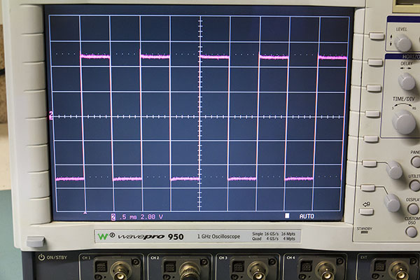
Generally tidy although the bottom of the case has several scratches and damage to the feet. You can see from the second shot that the traces
are quite noisy but Dave explains in
EEVBlog #601 (plus the follow-up
EEVBlog #610) why digital oscilloscopes have a tendency to
appear more noisy than analogue 'scopes and why high bandwidth DSOs in particular suffer from this problem.
I had a hunch that there wasn't actually anything wrong with the 'scope so was fairly pleased to pick it up at about half the seller's original price.
So, got it home and booted it up.
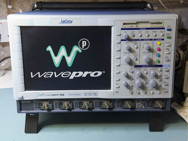
Sure enough once I had watched Dave's videos again my hunch proved correct - kicking in the 200MHz BWL and setting the acquisition length to a more reasonable 10k points reduced the apparent noise considerably. I like the large 10" LCD that these 'scopes have, although the resolution is slightly limited at 640x480.
Having a new toy means taking it apart, obviously - actually I needed to as someone had attached a huge security anchor to the 'scope - you can just see it in the last of the vendor's photos. I would quite like to remove it as it is huge, butt ugly and I don't especially need it but I wasn't sure whether it had been superglued to the side of the case or bolted through it so I needed to get the case off anyway.
That is actually trickier than it looks. The first thing to do is remove the back "feet" - the rubber bungs hide the screws. I must replace the cover on the PC card slot - this could be used for a PC card hard disk, or CF card plus adapter for storage but I don't have the software option installed to make it work -
bummer! 
Having removed the back legs it is necessary to remove the three screws securing the bezel at its base and then remove the bezel revealing a further seven screws (three across the top and two on each side) holding the top cover in place.
Having removed the top cover we now have access to the CPU card - which is actually much smaller than I thought it was going to be - it is worth pointing out at this point that these things are big and built like the proverbial brick dunny.
We can also see the fans....
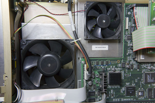
...two of them in fact, the larger is, well, enormous. Even the smaller is substantial and they are not especially quiet - I measured about 56dB SPL at 0.5m from the 'scope (ambient noise about 35dB SPL). The fan note is not too irritating but neither is it quiet, my 9354 (admittedly I swapped the fan on that one) registers 46 dB at 0.5m.
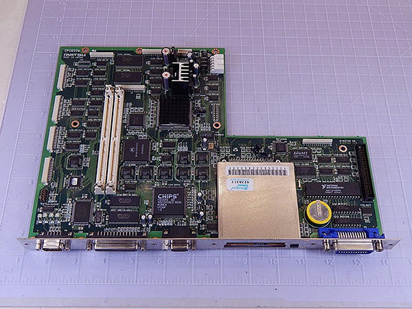
Unfortunately I can't see what the actual fan manufacturer or part numbers are without removing the fans which requires more dismantling. So we can look at the CPU card which is an Iwatsu CPU603e (bit of a clue there as to the processor architecture).
The CPU can take up to 512MB of PC-100 or PC133 SDRAM, I seem to have 128MB of PC-100 memory; I'm not sure if there is any benefit to increasing this.
Interestingly I found the older version of the CPU card on sale on ebay, thought I would include the photo for comparison.
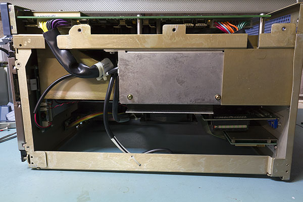
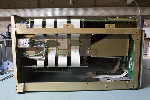
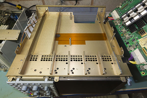
Side views. I didn't strip the chassis down far enough to get the fans or PSU out.
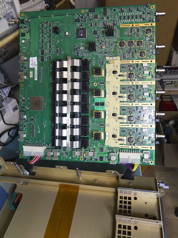
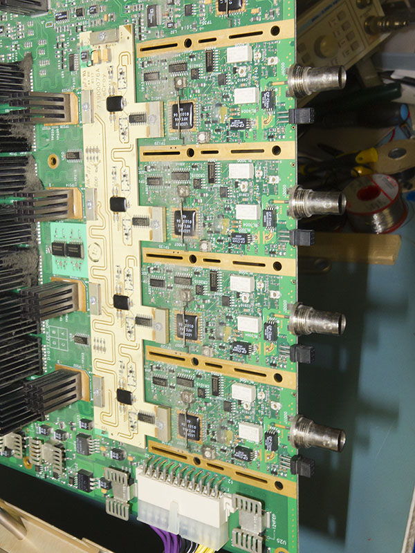
So, having had a look at the CPU let's flip the 'scope over and examine the business end of things. With the bottom cover off we can see the acquisition board - this side doesn't look all that exciting so the next step is to remove the screening - we need to do that to get the board out in any case.
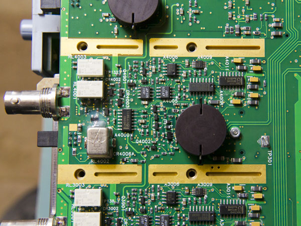
One of the input channels in detail.
Having got the screening off we can now remove the six screws holding the card in place, the ribbon cables connecting the acquisition card to the CPU and the external clock coax and finally swing it up to take a look at the board properly. This is a large PCB which occupies almost all of the base of the 'scope - approx 12" x 15".
The ADC's have some serious heat sinks attached. However I was very surprised to find that the airflow is not actually aimed at these heatsinks first. Air is directed through the square cut out holes over the front end circuits first and then backwards towards the ADC heatsinks in the centre of the board by channels formed by the front end screening.
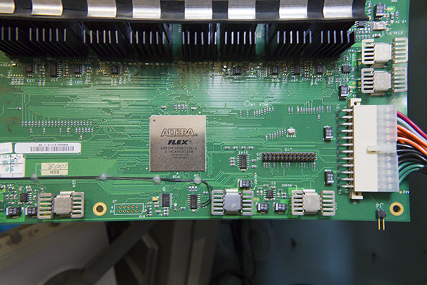
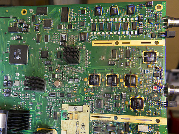
The acquisition board has an Altera EPF10k50 PLD for glue logic/control
Finally some more details of the front end modules, external trigger and CAL output.
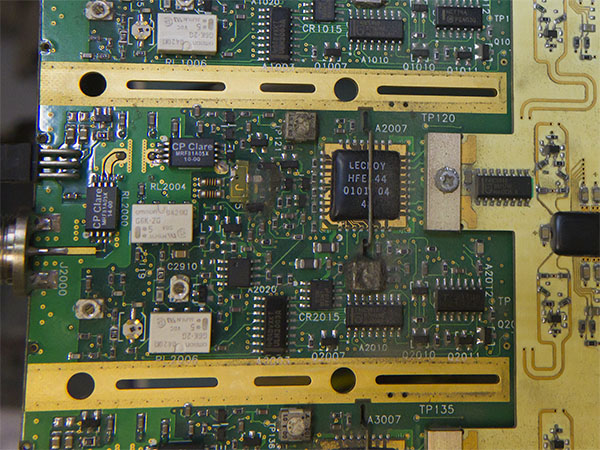
One thing which does surprise me is the number of trimmers in the input circuit, I expected that the adjustment on the input would be entirely electronic.
I hope everyone enjoyed the photos. It looks like I'm stuck with the security thing BTW. It is glued to the side of the case, probably with industrial cyanoacrylate. I might be able to remove the glue with some acetone but I would probably remove the paint along with it and make much more of a mess than just leaving it there. I broke off all the superficial plastic figuring out how it was attached which makes it less obtrusive so I'll probably just leave it.
Overall I'm pleased with the purchase. It's a lot of oscilloscope for the price. I considered buying a new 'scope but could not really justify the cost given that I would need something which is well out of the "bargain basement" of modern DSOs and I really can't justify the cost for hobby use.
Time to get a network port on the bench and hope that the 'scope's Ethernet card works


