Finally, it's here. I had no luck to get infamous 3458A affordable enough, so went to very familiar route, with
Keithley. Like some say it can't be enough DMMs, no matter how many one have.
As some members know, i'm Keithley addict in a way, and have few Model 2001 meters, which were violently abused and
tear down to pieces on daily basis, covering journey in
this thread at EEVBlog and
my own project tracker.
Welcome Model 2002 in it's beauty, probably smallest 8.5 digit meter on market. It's still current model, and
officially avalable thru
official manufacturer website, just like 20'year old 3458A

.
To my surprise this one don't require any fixing/repairing or other mess, very unlike my 20 year old 2001's

Everybody who saw Keithley 200x/7001/24xx/26xx ones, will know how 2002 look like, so I'll post overall view
and menu/settings tricks later.
PDF manuals.
As with all recent Keithley gear, schematics or detailed construction information is not available.
Best we have is repair manual troubleshooting hints, self-test diagnostics description and part list (which is helpful too).
For now we start with real stuff, teardown and
I actually shoot video-review (planned to be short, but it blew to 24 minutes). Sorry, my english require
lot of improvement and it's not my native, and it's almost my first video, so don't judge too harsh
And resources + hi-resolution photos of things inside below:
All photos clickable/zoomable
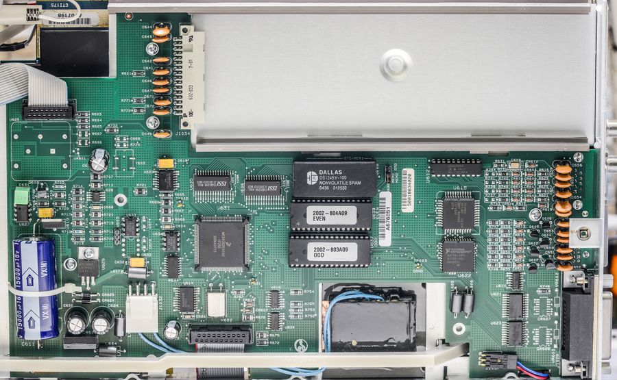
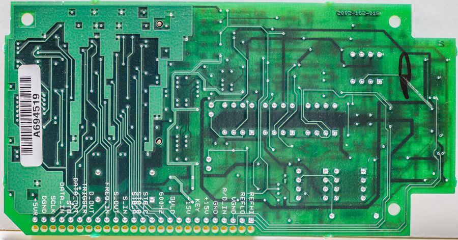
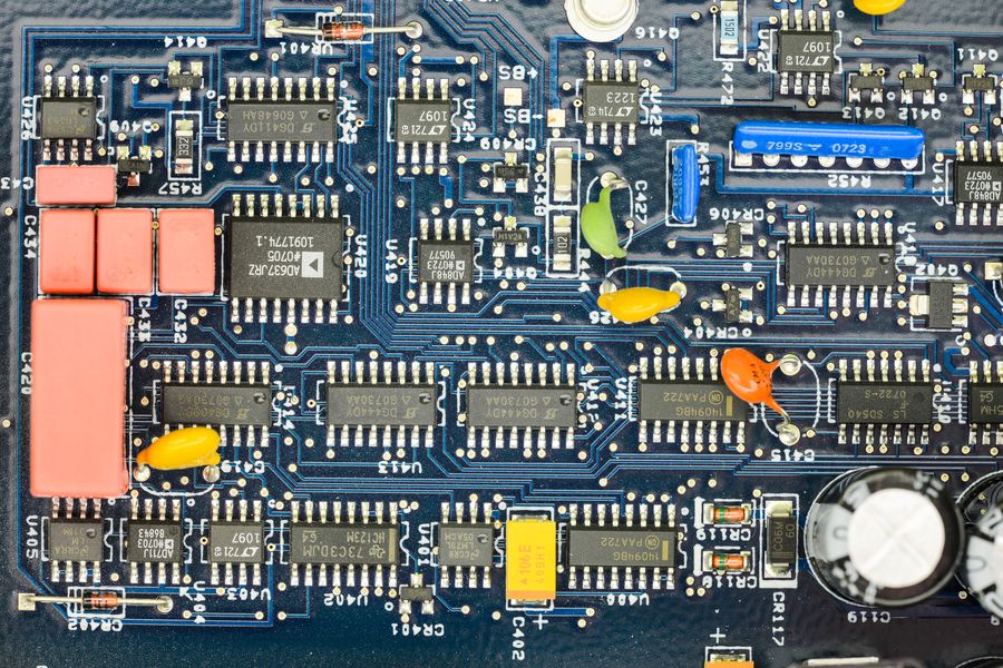
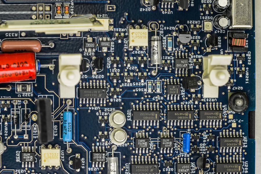
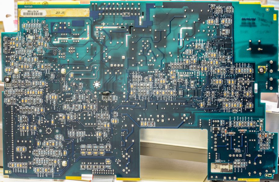
Digital board. It's 2001-142, Revision K. Very same board as in my second Keithley 2001.
Differences on BOM level:
* High-voltage DC-DC module (block near front panel connector) (+5V to filament VAC and +60VDC for VFD) moved from digital board to front panel.
* STD option used DALLAS DS1243 (NVRAM with Phantom RTC clock), MEM2 likely to use bigger version, such as DS1248 or DS1251
* Extra I2C 24C16 EEPROM on position U633 for calibration constants/data?
* Firmware for Model 2002
* Missing protection diodes on GPIB port interface (while
www.38hot.net BBS 2002 had them on)
* Small ALTERA MAX5064 CPLD for trigger-link replaced by TEKMOS 2001-801-A05 ASIC
* 4MHz clock moved to front panel too.
Analog board is different story tho...
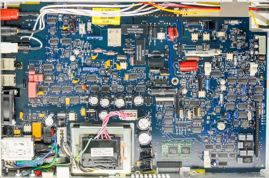
In general construction and functional units are same, but in critical areas using more precise components with tigther tolerances/less tempco.
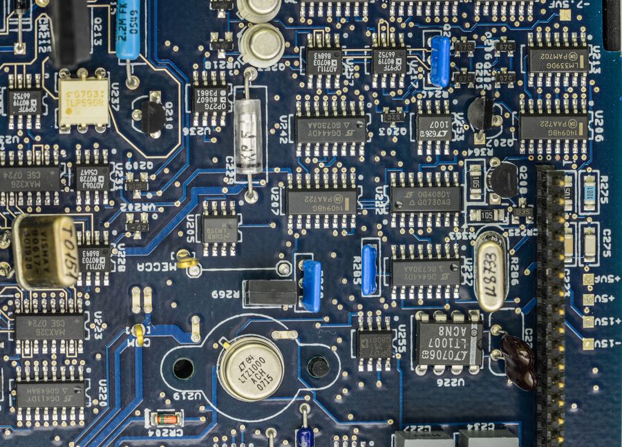
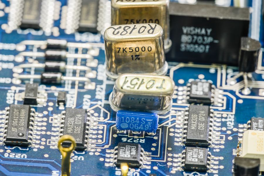
Voltage reference changed from aged/selected LM199/399 to LTZ1000ACH.
There are now two switching capacitor building blocks (Linear LTC1043CSW) paired with KEMET PC or PP film capacitors.
Current source for resistance is using Vishay foil's. Switching between ranges now using MAX326's.
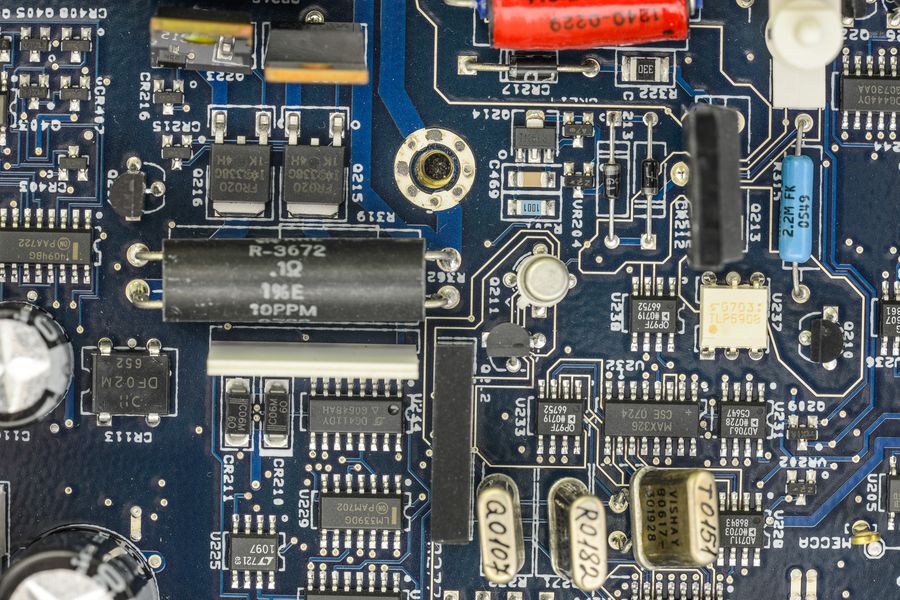
Ohm measurement is almost same, 0.1ohm 1% kelvin resistor (but better tempco, +-10ppm by label on it) + 0.91ohm and
Caddock 1737-53 network (same as 2001).
Same bootstrap circuitry as 2001's (four big caps near transformer) with avalance diodes between them,
same True-RMS AD637JR.
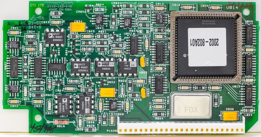
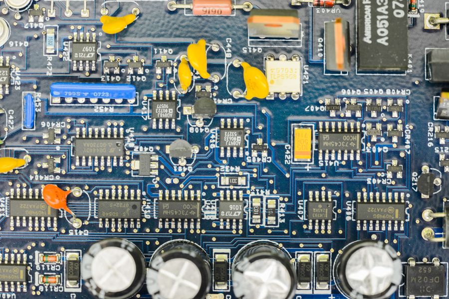
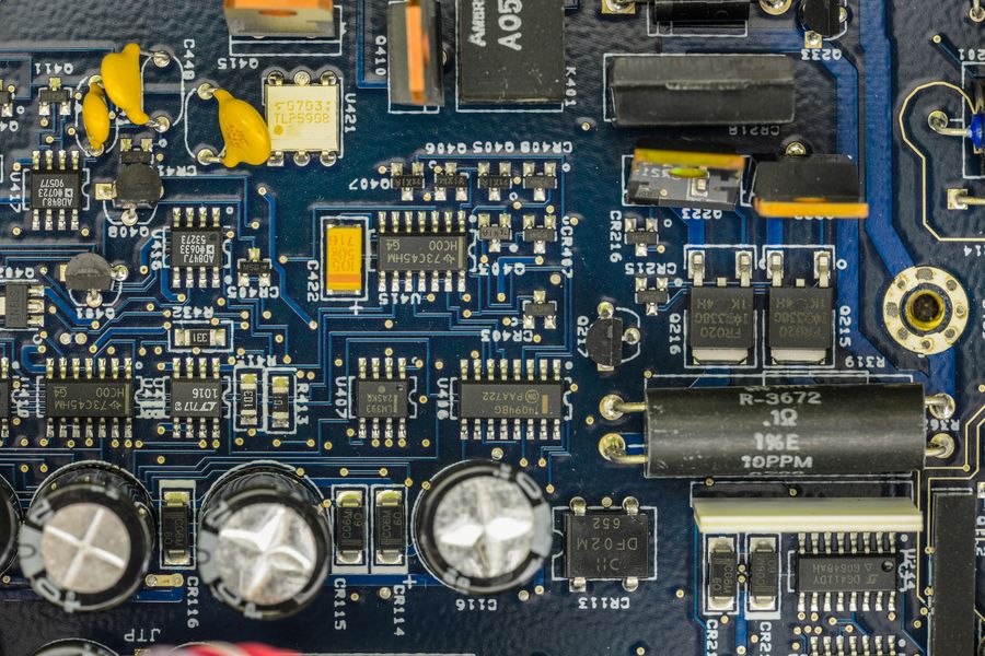
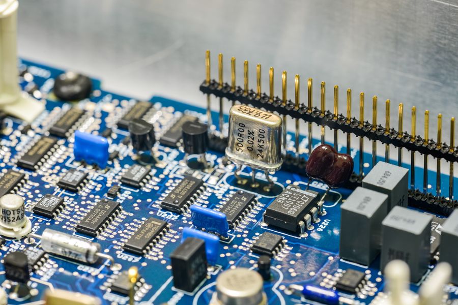
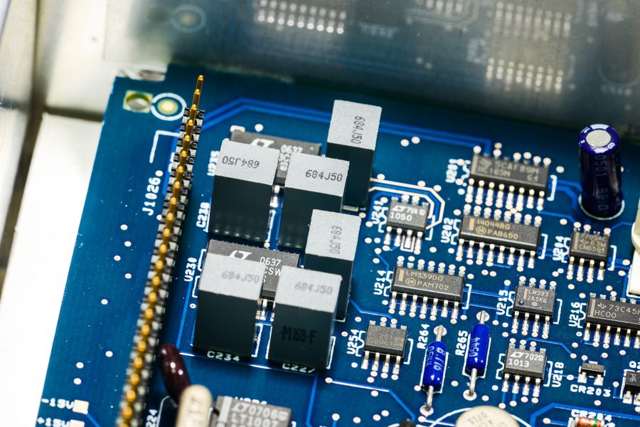
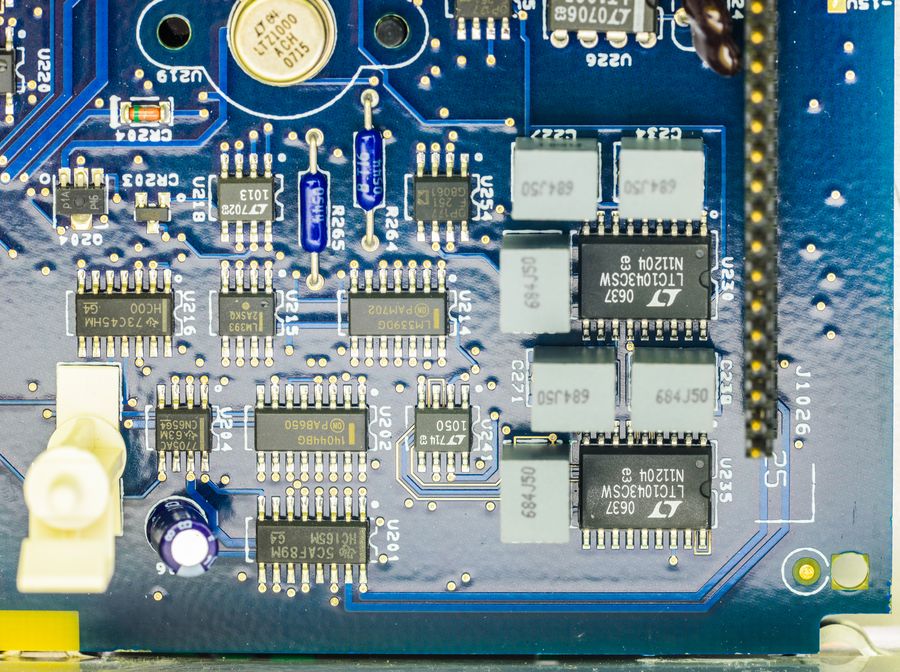
2002-162 4-layer PCB with ADC module now mostly completely SMT, designed in 1993 (yes, 21 years ago!).
It's revision B.
Featuring ALTERA EPM7160 in PLCC84 package, configured to 2002-802-A01 RTL, and clocked from 12MHz FOX XO.
As reminder, Model 2001 was using 7.68MHz with EPM7128 in PLCC64
Some resistors now are in SO-16 networks (R827 and R825 on left side)
Also I could not spot integrating capacitor, it's probably one of NP0 SMD caps.
Model 2001 ADC was using bulky film thru-hole cap rated to 400V.
No components on back side, only nicely labelled interfacing connector. Reference voltage supplied differentially,
REFLO and REFHI? I measured REFHI, it's 7.13..V
Let's go back to analog board...
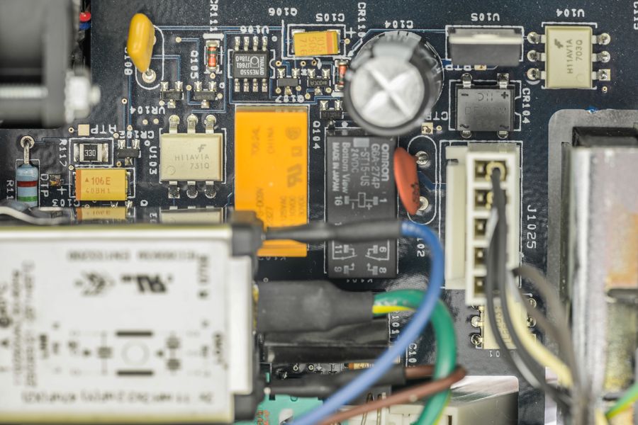
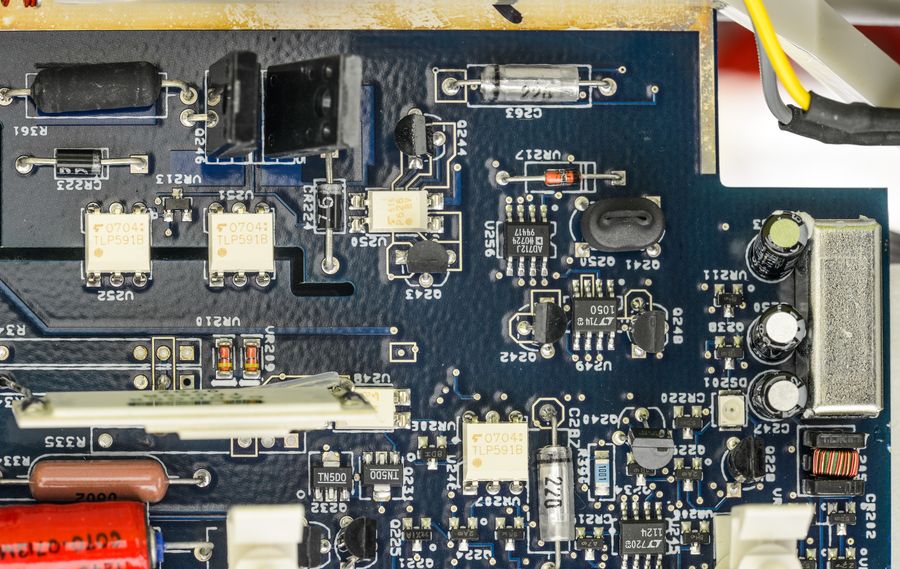
Mains switching / control curcuitry is same as in 2001. It handles selection 90-132 or 180-250VAC ranges automatically, as
well as provide frequency zero-cross signal for ADC to trigger in right at required NPLC cycles, to increase CMRR and PSRR.
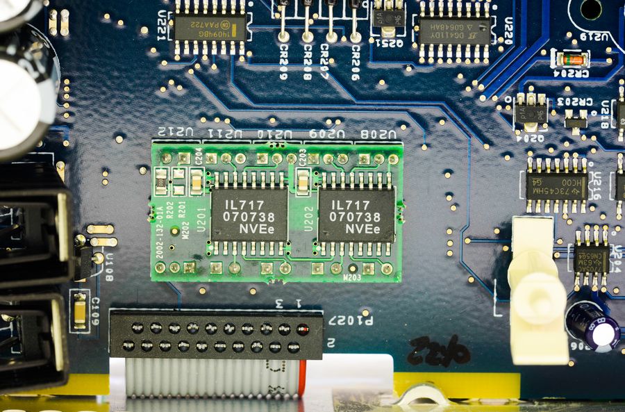
Optical isolation with digital board was done with separate daughterboard, labelled 2001-132-01A. It carry two
NVE IL717, which
are four-channel 110Mbps digital isolators. But if look closely - pin interface between boards matching original TLP582's,
so my guess that TLP582 couples were difficult to get in stock, so they added this adapter board, to keep analog board
design intact.
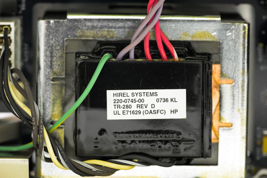
Power transformer have same configuration and pinout as 2001, marked HIREL systems, TR-280 Revision D.
It have magnetic shielding with copper foil around winding.
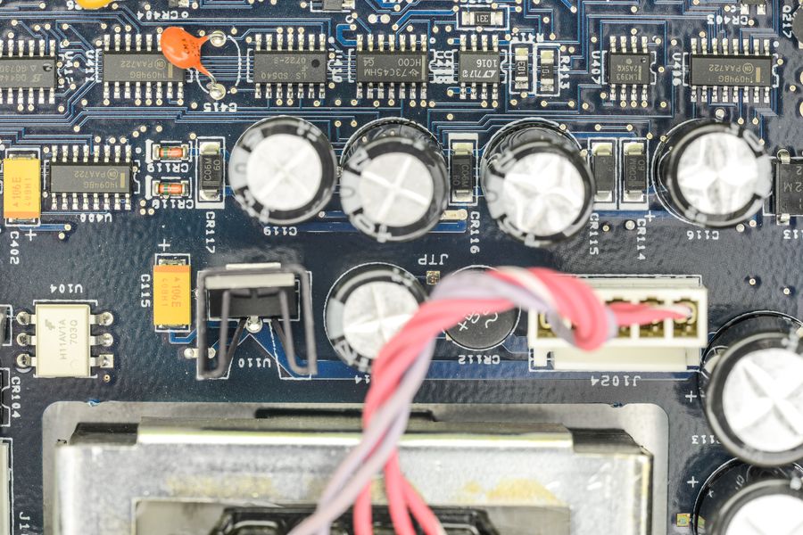
2002 equipped with very similar or same bootstrap circuitry, which provides +39 and -39V for analog needs, as well as +8/-8VF
for ohm/amps measurements. Those pesky C116,C115,C118,C119 capacitors tend to leak with age/elevated temperatures and
commit complete disaster on PCB, eating traces, leaking electrolyte all over precision circuits... This meter is only 8 years
old, so they are still fine, but next year I will replace them to freshies for sure
Input side.
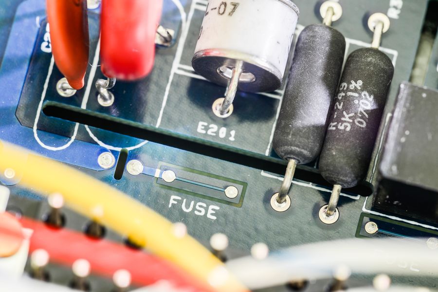
PCB Fuse
Old 2002 analog board don't have this, at least from what I can say looking on crappy photo
from chinese forum mentioned before. 2001 also don't have this. Wonder what that one does, maybe some
last step emergency protection?
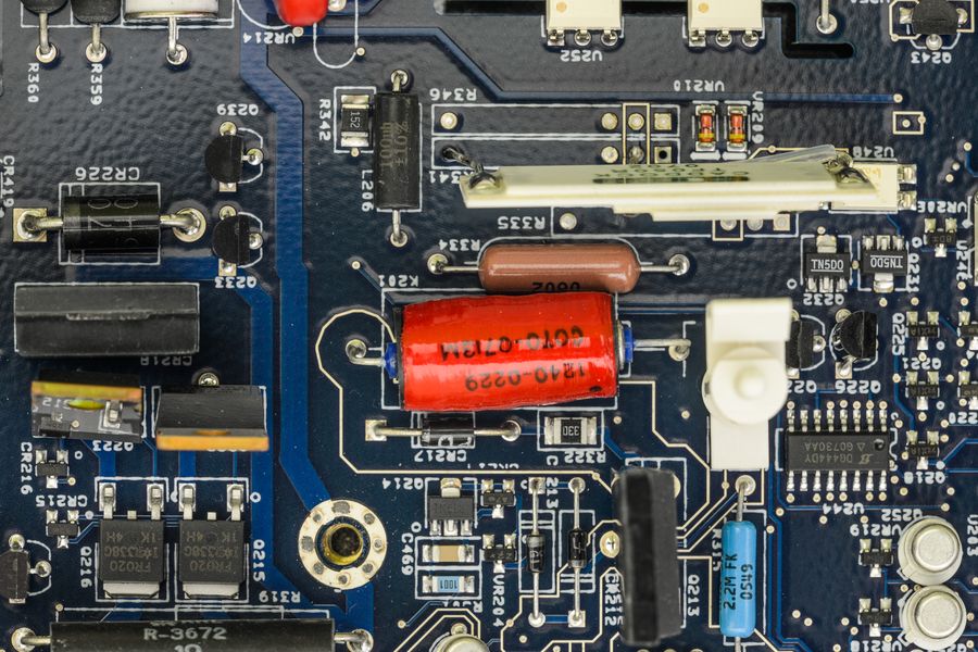
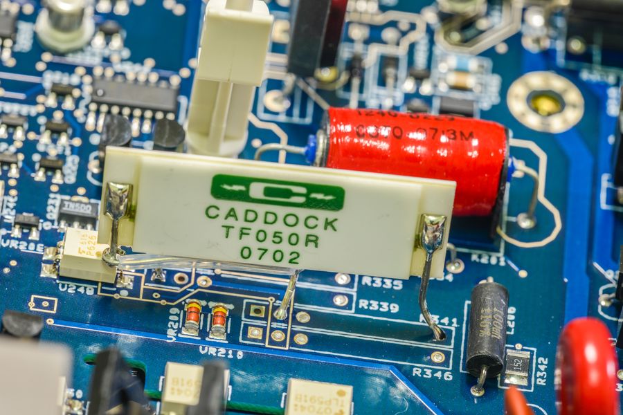
Combined Caddock resistor network.
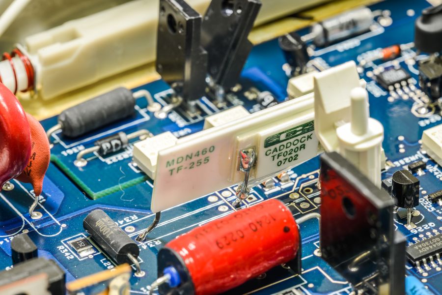
Consists from two resistors, bigger TF050R, and glued TF020R on back of it.
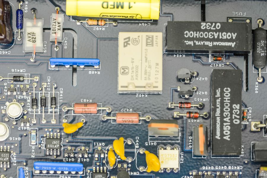
Reed relays made by Americal Relays Inc in this meter, A051A300H0C model, which likely to be custom, and
usual DK1a1b-6V relay. Circut here same or almost same as 2001.
Old 8-bit DAC from 2001 meter (MP7528) got replaced by same thing, which is Analog Devices AD7528, dual matched DACs, which
are used for TRMS filter circutiry to adjust operation of meter's AC conversion block. This section is very similar or same to 2001.
Same with TrueRMS convertor itself, which is AD637JR with bunch of DG444,DG408 and DG41 switches around.
There are also AD848J, LT1097, LT1223, AD711J and LM79L05A -5V negative LDO in this area.
All same stuff as 7.5 digit Keithley brother.
7V VREF:
Famous Linear ultra-zener reference, LTZ1000.
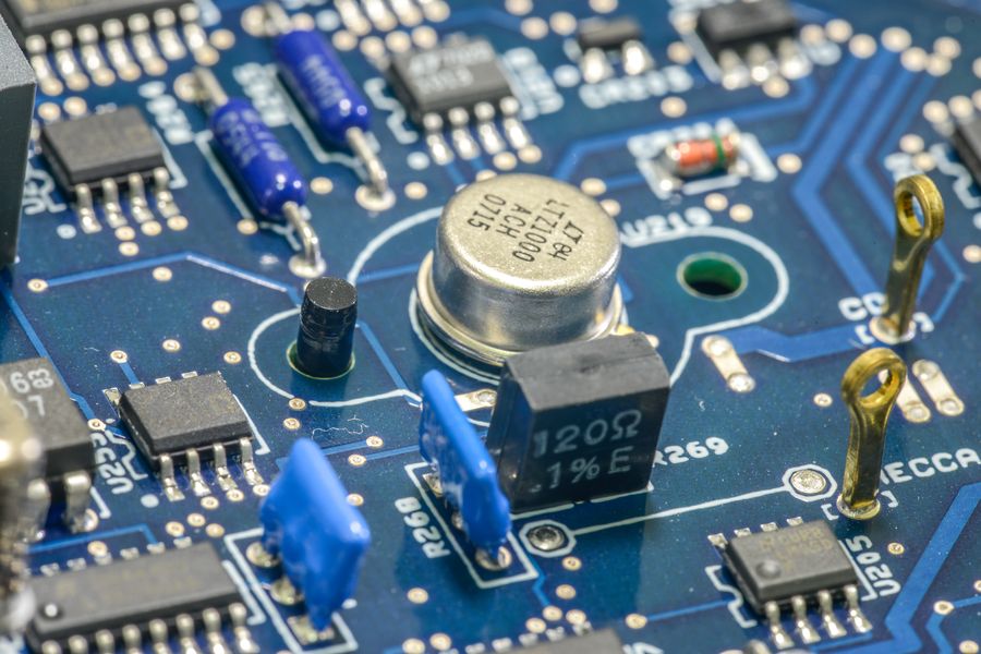
It have dedicated plastic cup from both sides of to seal reference from any airflow and reduce temperature influence from rest of the world.
Probably it's reference standard connection, can see 120 ohm 0.1% resistor nearby, as well as few PTF56 low-tempco resistors.
Also two blue resistors networks nearby, but those may not be related to voltage reference, at least one of such networks
can be found in 2001 too.
Back side of PCB with LTZ.
LTZ have popular companion Linear LT1013 in SO8 package with Q204 is heater drive transistor in SMT package.
There is also temperature sensor somewhere on board, as Keithley 2002 can measure it's internal temp, which it reports as
delta to calibration temperature. This measurement is readily available by temperature function, by selection INTERNAL TEMP mode.
In my case, reported value was -3.4°C , with ambient temp +24°C, while meter run around half-hour.
If I just power on cold meter it says -23.2°C and descreasing (to lesser delta) while meter warms up.
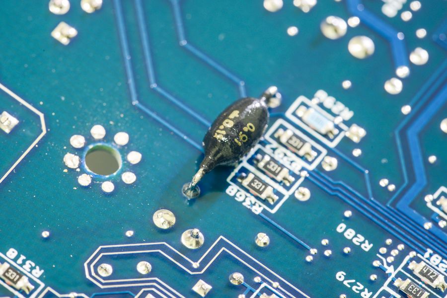
Current measurement parts, two MOSFETs to switch ranges for high amp ranges, long Vishay Z201 resistor (R277).
Right side of photo is for resistance measurements.
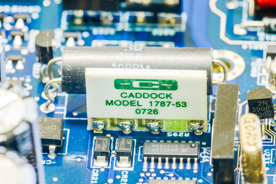
Same CADDOCK as in 2001 for low current ranges. This is actually standard network 1737-53, available even on Digikey
And not so standard Vishay PG hermetic oil-filled bulk foil resistors, with tolerance 1%. Absolute tolerance is not so important
in this case, as it's software calibrated anyway, but stability and tempco is what needed most. And there are only
few resistors on market which are better than these.
Resistors here used to set precise currents for sourcing thru unknown resistance for measurement. Switching is done
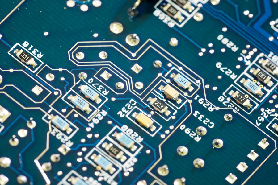
by MAX326's nearby. All heavily guarded and carefully designed precision voodoo.
There is also lonely Vishay PG hermetic oil-filled resistor network with tolerance 0.02% and 500.00 + 24500 resistances in it, likely setting gain for buffer amplifier (which is LT1007ACN8
in DIP8 package nearby). Switching of different gains done by DG444 and DG408 switch IC's nearby.
Switching capacitor dividers/multipliers, using film KEMET capacitors and Linear LTC1043CSW blocks. Keithley 2001 meter have only
one LTC1043 in DIP package.
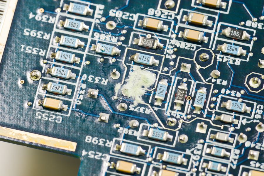
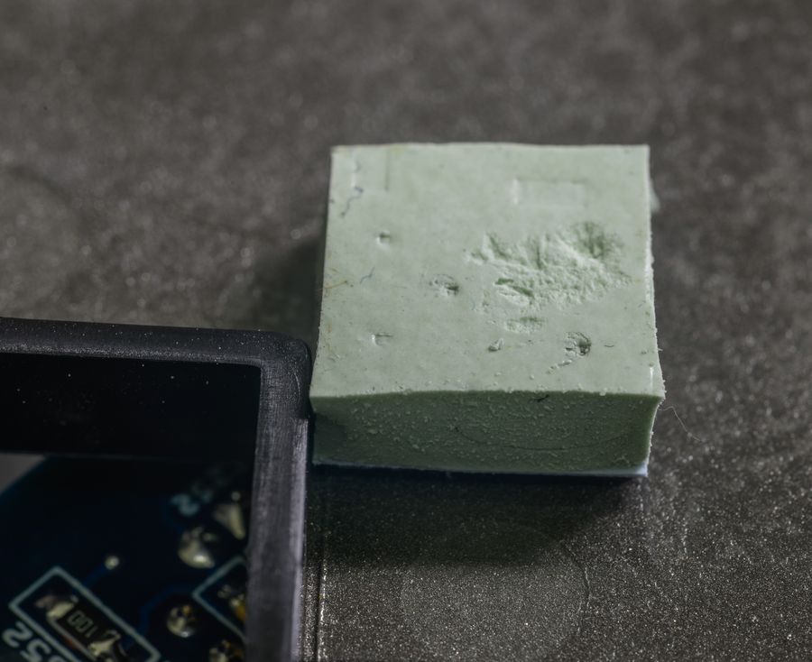
Blob in center look like corrosion/salt, and I actually cleaned it carefully, but that was waste of time.
Why?
Because it is from insulator sponge, placed on protective/shielding/thermal bottom cover.
More bottom side components.
0.91 ohm current sensing resistor shunt, unlike 2001, here its populated on bottom side of PCB. On 2001 it was right under 4-wire
resistor.
Those smudges/fingerprints seem to be on soldermask, as they are not erasable with alcohol. Looks dodgy, but it seem
not affecting performance..
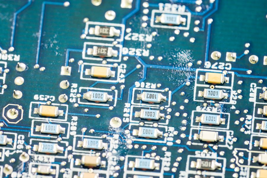
Dual guard traces around sensitive high-impedance resistance measurement circuitry. Beauty!
Overview of bottom side of analog board, without cover.
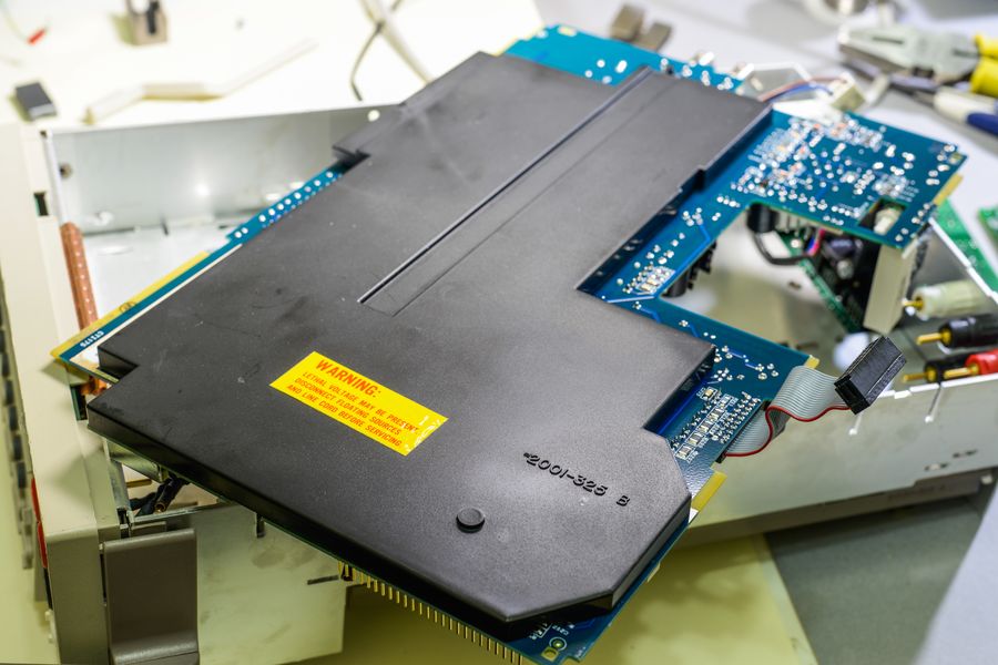
Back cover/shield is same as 2001's, and actually bearing 2001-325 Rev.B tag on it.
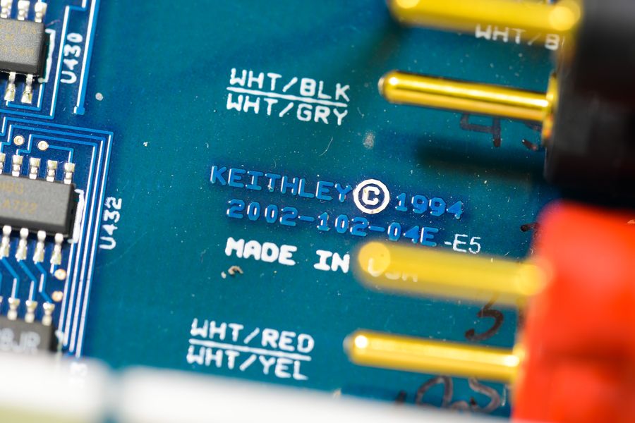
Analog board is labelled 2002-102-04E-E5, designed in 1994, made in USA
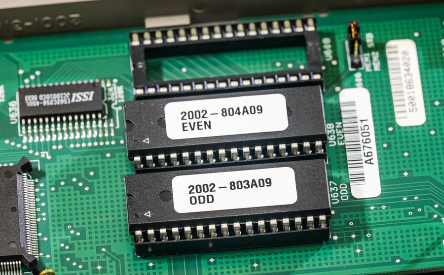
FirmwareI have A09.
ROM, ODDROM, EVENAs usual, now I have tracker and documentation project on
my redmine for Keithley 2002.
Anybody welcome to download available stuff or participate in related endavours.
That's it for now..
Feel free to ask any suggestions, requests what can do/test with this meter.
I don't plan to do official calibration for it (as it's double price of 2001) at this moment, and
it seem to be pretty spot on already, at least it matches both Kei2400 and Kei2001 (which are still
only 3 weeks period from adjustment/cal) real close.
I do plan to work later on recovering schematics of Model 2002 as well, but have to finish 2001's one prior to that.
Want to try morph some functions from 2002 into 2001 (NPLC range, LTZ1000 reference, 8.5 digit native mode), as
already digital side of both meter's is same.
If anybody around have Model 2002 too, and can open it and remove analog board cover for internal photos - such
work greatly appreciated! I want collect photo of different revisions/years for 2001/2002 series, but not going to
buy every single meter out there. Only 2002 photos found online were some old unit (1997 datecode) on bbs.38hot.net.
Obviously not much owners tear down 6K$ MSRP DMM's, so that's why...
BR,
TiN P.S. Video is uploading, it will take couple hours, internet is not good here when need upload 2GB of FullHD video to tube


