Author Topic: Network analyser: LF Pi network recommendation?  (Read 6010 times)

0 Members and 1 Guest are viewing this topic.

Offline nctnicoTopic starter

  • Super Contributor
  • ***
  • Posts: 27895
  • Country: nl
    • NCT Developments
Network analyser: LF Pi network recommendation?
« on: July 28, 2016, 11:05:09 pm »
I recently got a network analyser (10Hz to 300MHz). One of the things I bought it for is measuring inductors. That is possible using a directional bridge (got it) or a so called Pi network. Unfortunately I have no idea what the Pi network should look like and whether it can be build or needs to be bought. Double bummer is that entering 'pi network' into Google gets me all I don't want to know about setting up the network on a Raspberry Pi.
Long story short: I'd really appreciate it if someone could point into the right direction.
There are small lies, big lies and then there is what is on the screen of your oscilloscope.
 

Online Performa01

  • Super Contributor
  • ***
  • Posts: 1712
  • Country: at
Re: Network analyser: LF Pi network recommendation?
« Reply #1 on: July 29, 2016, 08:22:33 am »
Unfortunately, I cannot answer that question either, but it reminds me on a test fixture I’ve built some 30 years ago in order to measure small inductors at appropriate frequencies, which happens to have a Pi structure.
It was intended to be used with a scalar network analyzer – in fact an SA with TG and out of my memory, it looked like this:


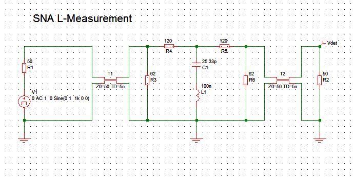
Basically a 20dB attenuator that helps to keep the port impedances reasonably constant and a reference capacitor that forms a series resonance circuit with the unknown inductor.

The following graph shows the result for 100nH, 1µH and 10µH:


With a reference capacitor of 25.33pF, resonances will occur at 10MHz for 10µH, 31.6MHz for 1µH and 100MHz for 100nH, which should match the usual frequency range for these inductor values, but can easily be adapted of course.

The quality of the inductor can be estimated by the max. attenuation at the series resonance frequency. 20dB additional attenuation (= 40dB total) means a series resistance of 18 ohms, likewise 40dB (60dB total) would indicate a series resistance of 1.8 ohms. From that it should be easy to calculate the Q of the inductor, provided that a high quality capacitor (maybe an air trimmer) is used and the quality of the resonance circuit is almost entirely determined by the inductor.


Offline CJay

  • Super Contributor
  • ***
  • Posts: 4136
  • Country: gb
Re: Network analyser: LF Pi network recommendation?
« Reply #2 on: July 29, 2016, 02:24:49 pm »
I recently got a network analyser (10Hz to 300MHz). One of the things I bought it for is measuring inductors. That is possible using a directional bridge (got it) or a so called Pi network. Unfortunately I have no idea what the Pi network should look like and whether it can be build or needs to be bought. Double bummer is that entering 'pi network' into Google gets me all I don't want to know about setting up the network on a Raspberry Pi.
Long story short: I'd really appreciate it if someone could point into the right direction.

Are you sure they don't just mean putting the inductor into a Pi filter and measuring response?

http://www.radio-electronics.com/info/rf-technology-design/rf-filters/simple-lc-lowpass-filter-design.php
 

Offline joeqsmith

  • Super Contributor
  • ***
  • Posts: 11853
  • Country: us
Re: Network analyser: LF Pi network recommendation?
« Reply #3 on: July 29, 2016, 02:52:52 pm »
I recently got a network analyser (10Hz to 300MHz). One of the things I bought it for is measuring inductors. That is possible using a directional bridge (got it) or a so called Pi network. Unfortunately I have no idea what the Pi network should look like and whether it can be build or needs to be bought. Double bummer is that entering 'pi network' into Google gets me all I don't want to know about setting up the network on a Raspberry Pi.
Long story short: I'd really appreciate it if someone could point into the right direction.

I have no idea what you bought.  If its a VNA, you should be all set.  I am guessing some sort of scalar.  If its like my old HP3589A, I can add an external "directional coupler " to measure the incident and reflected.   From this I could easily measure RLC.  I picked up a coupler for it but never wrote any software for it.  I own a very old HP8754A that I wrote a fair amount of Labview code to control it.  The directional couplers are built into the S parameter test set.  Video showing the software for the 8754A.


Offline nctnicoTopic starter

  • Super Contributor
  • ***
  • Posts: 27895
  • Country: nl
    • NCT Developments
Re: Network analyser: LF Pi network recommendation?
« Reply #4 on: July 29, 2016, 03:29:29 pm »
It is an Anritsu MS4630B network analyser. It has a generator output with an internal power splitter and two input ports (R and TA). It has the possibility to measure RLC networks using the reflective and transfer method and plot things like Ls, Cs, angle, Q, D, ESR, etc in various graphs so it is pretty complete (what your software does looks very familiar to what I have seen on the MS4630 so far). I have made some measurements using the directional coupler (10kHz to 200MHz) but I'd like to get more confident I'm doing things right so I like to be able to obtain the same results using a different method. I have copied the following picture from the manual which shows how everything should be connected for measuring impedances using the -what Anritsu calls- transfer method.

The connections on the left are the outputs, the ones on the right are the inputs so one signal goes through the Pi network to the TA input and the other output goes directly to the R input.
« Last Edit: July 29, 2016, 03:32:45 pm by nctnico »
There are small lies, big lies and then there is what is on the screen of your oscilloscope.
 

Offline rfeecs

  • Frequent Contributor
  • **
  • Posts: 807
  • Country: us
Re: Network analyser: LF Pi network recommendation?
« Reply #5 on: July 29, 2016, 05:39:43 pm »
Since the manual refers to measuring a resonator using a pi network, it may be referring to IEC 444 method of measuring quartz crystals with a pi network.

This may give you some search terms.

It seems like an obscure way to do a specific type of measurement.  Personally I wouldn't pay much attention to it and focus more on directional coupler or bridge type measurements.
 

Offline Earendil

  • Regular Contributor
  • *
  • Posts: 102
  • Country: hu
Re: Network analyser: LF Pi network recommendation?
« Reply #6 on: July 30, 2016, 01:01:43 pm »
The Pi network should be just a "Pi" shaped circuit consisting of 3 elements. 2 capacitors and an inductor (or vice-versa). You can find more about it by googling pi network impedance matching.

I think here it is employed to match the characteristic impedance of the DUT to 50 ohms. Normally with the reflection method you can only measure impedance precisely around 50 ohms because the VNA measures the reflection coefficient of the DUT and the numerical error becomes large at the two ends (-1 and 1).

A useful reference in the topic is the Keysight Impedance Measurement Handbook:
http://literature.cdn.keysight.com/litweb/pdf/5950-3000.pdf

I also kind of remember seeing some Keysight/Agilent/HP publications about using jigs / alternative ways of connecting the DUT to a VNA but I can't find it right now unfortunately.

Edit: The Pi network jig is briefly described here: http://cp.literature.agilent.com/litweb/pdf/5988-0728EN.pdf
« Last Edit: July 30, 2016, 10:52:51 pm by Earendil »
 

Offline nctnicoTopic starter

  • Super Contributor
  • ***
  • Posts: 27895
  • Country: nl
    • NCT Developments
Re: Network analyser: LF Pi network recommendation?
« Reply #7 on: July 30, 2016, 03:54:05 pm »
@Earendil: Thanks for postings the links.
I have been doing some experiments based on Performa1's circuit as well with the IEC 444 method in mind.
There are small lies, big lies and then there is what is on the screen of your oscilloscope.
 

Offline Earendil

  • Regular Contributor
  • *
  • Posts: 102
  • Country: hu
Re: Network analyser: LF Pi network recommendation?
« Reply #8 on: July 30, 2016, 09:01:52 pm »
This Pi network method is described in every document I've seen as a way to measure resonators.
I believe a better and in fact easier technique would be to use the series-through / shunt-through configuration and measuring S21 (insertion loss). Those are the alternatives ways of connecting the DUT to the VNA I was referring to.


Offline nctnicoTopic starter

  • Super Contributor
  • ***
  • Posts: 27895
  • Country: nl
    • NCT Developments
Re: Network analyser: LF Pi network recommendation?
« Reply #9 on: July 31, 2016, 07:03:55 pm »
From the pictures it seems a PI network is measuring S12 but at a lower impedance. Perhaps to keep the impedances at the source and input more closer to 50 Ohm. I have put a PI network together using two pi-pad attenuators / impedance converters to make a 12.5 Ohm-ish PI network jig (mine is 13.2 Ohm because I didn't have 68 resistors and used 22+47=69 Ohm).


Measuring the Q factor for the inductor I want to use seems OK up to 200kHz or something (which would suffice for the project at hand) and in that region the transfer measurement with the PI jig and the reflection bridge results are the same. From there the results are just plain wrong with what they should be in theory. I think somehow the measurement loses the accuracy required to determine the Q factor. The formula for the Q factor is 2*pi*f*L/R (=Z/R) where R is the real part of the impedance. I see that the resistance starts to get way off at higher frequencies. With many inductors the DC + skin effect AC resistance is only a few Ohms so I'm either at the limits of what the instrument can do or my test setup / settings aren't up to the task.

Just for fun I attached an 8 MHz crystal to my PI jig and let the MS4630B determine it's circuit model:

I used the component values in Pspice and -how surprising- it came up with the same results.
« Last Edit: July 31, 2016, 07:33:56 pm by nctnico »
There are small lies, big lies and then there is what is on the screen of your oscilloscope.


Share me

Digg  Facebook  SlashDot  Delicious  Technorati  Twitter  Google  Yahoo
Smf