Author Topic: Fluke 801BR partial teardown and a bit of repair  (Read 6243 times)

0 Members and 1 Guest are viewing this topic.

Offline babysitterTopic starter

  • Frequent Contributor
  • **
  • Posts: 899
  • Country: de
  • pushing silicon at work
Fluke 801BR partial teardown and a bit of repair
« on: January 21, 2017, 07:40:59 pm »
John Fluke Mfg. Co. Inc. proudly presents


I recently got a shipment of 3 devices considered dead for a price slightly over shipment costs. This one is very close to working condition, but acts up when it runs for a while. Anyway, time for some pretty photos with lots of resistors!

It's a differential DC voltmeter with VTVM-mode up to 500V and 5 decades., the Interwebs unfortunately are devoid of documentation. Its employing both vacuum tubes and solid state components, its appearance and the low serial number let me believe its from the sixties.

After a slow, soft start with a variac it came to life immediately without bigger problems and with a whirring sound . Both differential and VTVM modes basically work. However, it has two problems:

  • Temperature drift: Its quite accurate after turn on but then drifts away.
  • The wheel with the printed digits attached to the 4th decade switch has changed shape, needs some force to turn

No realy troubleshooting has been done yet.

Enough talk, here are the pictures:

Left front panel with center-zero instrument
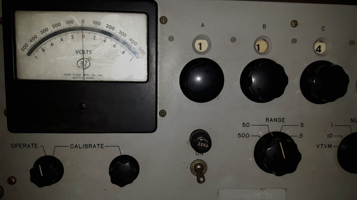
The instrument is pretty big and still white, the crud you see was on the glass.

Turning the "operate/calibrate" switch to the right, you can actually adjust the needle to zero. This is possible when cold, later the rightmost adjustment position is to the left of the zero. There are two stacked potentiometers with a mechanical dead-band for the adjustment!


Right front panel with the decade switches

Also, polarity  switches, mode/range selectors and input connectors are here.

Top view with cover removed
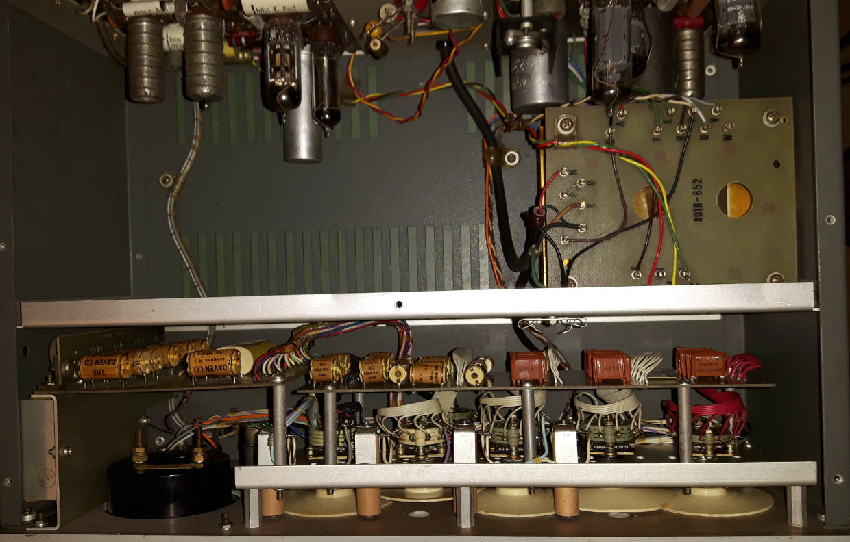
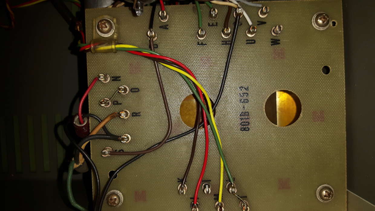
Transformer connection board. At the rear cover is a sticker which tells you how to connect for 0.115 or 0.23 kV mains.
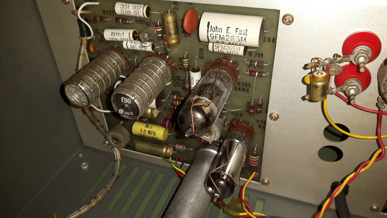
Left side PCB: Some tubes, one of them a voltage stabilizer (0A2) and a vibrating relay. Either chopper-amp or vibrator.
Right side PCB: Tube-solid state mix :)

The resistor strings that belong to the decade switches to select voltage division ratio

Those are made by Fluke (at that age maybe John Fluke himself), wirewound on (mica?) plates and laque-covered

Those are made by Daven.


« Last Edit: January 21, 2017, 08:25:27 pm by babysitter »
I'm not a feature, I'm a bug! ARC DG3HDA
 
The following users thanked this post: guenthert

Offline mmagin

  • Frequent Contributor
  • **
  • Posts: 610
  • Country: us
Re: Fluke 801BR partial teardown and a bit of repair
« Reply #1 on: January 21, 2017, 10:14:57 pm »
This should get you started.
https://archive.org/details/FLUKE_801_Army
I think I have a PDF of another version of the manual, I'll follow up when I'm home.
 

Online Gyro

  • Super Contributor
  • ***
  • Posts: 10008
  • Country: gb
Re: Fluke 801BR partial teardown and a bit of repair
« Reply #2 on: January 21, 2017, 10:19:44 pm »
Wow, I never realized there was an overlap between the era of valves and ribbon cable!  :o
Best Regards, Chris
 

Offline mmagin

  • Frequent Contributor
  • **
  • Posts: 610
  • Country: us
Re: Fluke 801BR partial teardown and a bit of repair
« Reply #3 on: January 22, 2017, 02:25:19 am »
http://www.liberatedmanuals.com/TM-11-6625-599-45.pdf
Is the other manual I've found.  Don't be scared by the radiation warning, it's just one of the VR tubes that has some kind of source in it so it reliably discharges.  I haven't found a full fluke manual.  I think there might be one for the 803b out there in the web, I think it's an 801b plus limited AC capability.

So, It looks like the rackmount version of the 801B (Serial number 708) which I have.  (It was fixed up nicely by a previous owner.)

Yours is not the version with the suffix that indicates a zener reference, so it should have a Weston cell inside.  It's an H-shaped glass tube in protective padding in a smaller metal housing.  A couple wires will lead from it to a PCB -- don't expect it to read correctly except on a high impedance meter, and never short it out.  Assuming it is still functioning (mine is), after shipping it may take days or weeks to stabilize.

When you hold the switch in the calibrate position and adjust the pot, you're calibrating the 500V supply based on the Weston cell.  In VTVM mode it's just a simple DC VTVM, but in the other selections the digits and the 500/50/5/.5 switch use a Kelvin-Varley divider to provide a reasonably precise voltage, and the null meter (sensitivity governed by the 10/1/.1/.01 selection) compares it with the input voltage.  In properly working order it's around the accuracy of a 4.5 digit meter and with the meter nulled, theoretically infinite impedance.

The calibrate pot is a dual-gang pot (both gangs in series) that deliberately has some mechanical slop in the mechanism, you turn the knob and you're turning both, but when you turn it back (to tweak the last bit), you're only turning the smaller value pot, thus giving finer control.  I thought mine was broken and I replaced it with a newer (but good wirewound low-TC) pot, and only later when I got an HP 419A which uses the same scheme (and explains it in the manual) did I realize it was intentional.  Fortunately I did keep the old pot.
 

Offline mmagin

  • Frequent Contributor
  • **
  • Posts: 610
  • Country: us
Re: Fluke 801BR partial teardown and a bit of repair
« Reply #4 on: January 22, 2017, 02:27:51 am »
Oh, derp, I forgot, I bought a (print) 801B manual sometime ago, let me see if I can scan it this weekend.
 

Offline Dr. Frank

  • Super Contributor
  • ***
  • Posts: 2425
  • Country: de
Re: Fluke 801BR partial teardown and a bit of repair
« Reply #5 on: January 22, 2017, 06:43:19 am »
Beautiful..very similar to the 803B, which I often repaired in 1980..1982.
Your unit has the unsaturated Weston cell, located to the left of the movement, in that aluminium case.
Here's a picture of these out of my (hi)story Weston cell thread:


If the zero of the differential chopper amplifier drifts too much, then the mechanical chopper relay is probably defect.
Seems, that the army manuals cover your instrument.
Best thing inside is the KV divider, and that you may measure 500V with zero current loading.

Frank
« Last Edit: January 22, 2017, 11:53:59 am by Dr. Frank »
 

Offline babysitterTopic starter

  • Frequent Contributor
  • **
  • Posts: 899
  • Country: de
  • pushing silicon at work
Re: Fluke 801BR partial teardown and a bit of repair
« Reply #6 on: January 22, 2017, 12:16:45 pm »
Hm, much feedback for a device I didn't find too much about except sales offers on the first pages of googling. =)

So far i understood it's handling and the fact that it can measure its own drift is somewhat satisfying. Not a bad catch (together with a not-yet-working wavetek 3001 and a fluke 825ar or 815ar, as I expected them all to be DOA. I paid just a little north of the shipping and handling.) 

I will post something sometimes here but the main part will be on my webpage: http://dg3hda.de/doku.php?id=fluke_801br

@Gyro: Oh yes why,  its for the computer so of course flat ribbon cable... the analog-ratio-calculator bus cable! :)

@mmagin: Thanks for the pointer to the manual and the other hints! Its certainly a weston-cell - no /AG suffix -  that comes as a surprise to me, as there are some solid state parts I considered it using a zener. Radiation from a VR does neither annoy nor surprise me (Being a radio and tv tech but from a way later era, started my professional training in Y2K).  Care and feeding of weston cells I know at least in theory. I suppose my HP3456 or the workplace 34401A is high-imedance enough at least to take a short measurement with filter and autozero both off. Or i will use one of them to null against a KVD-divided Zener reference.

@Frank: Oh so you have some history with thi kind of device, too! 

I'm not a feature, I'm a bug! ARC DG3HDA
 

Offline babysitterTopic starter

  • Frequent Contributor
  • **
  • Posts: 899
  • Country: de
  • pushing silicon at work
Re: Fluke 801BR partial teardown and a bit of repair
« Reply #7 on: January 24, 2017, 12:56:48 am »
Not much was going on this evening with the good ole 801 - some cleaning and the mains cable had to go due to brittle isolation. The cable feed-trough is harvested and will serve the next cable too. That means i will not operate it until I have a new cable. So long, only cold tests.

A quick check of the chopper relay NC contact has shown less than 500 Miliohm (how much is from the probes?) on a handheld, seems to be not completely gone, and the rattling noise during operation sounds like its chopping at least.
A quick look at Farnells Reed SPDT relay menu revealed several which are ok from coil voltage but

The spring you see on the separating wall between the transformer and the KVD resistors seems to be a courtesy to the service personnel - it actually is useful as a ground connection point for up to two 4mm lab jacks!

The 0A2 btw is emitting a glow, so it should be regulating. V104, a 0G3, is not visible due to metallic shield.

I'm not a feature, I'm a bug! ARC DG3HDA
 

Offline babysitterTopic starter

  • Frequent Contributor
  • **
  • Posts: 899
  • Country: de
  • pushing silicon at work
Re: Fluke 801BR partial teardown and a bit of repair
« Reply #8 on: January 27, 2017, 11:48:13 pm »
At least it has a new cable now. The old one had flakes coming of the inner isolation and the PE resistance changed when I moved the cable inlet to the Schuko mains plug. Mr. VDE might be not amused when he sees that i soldered the new one to the old posts, reusing the old strain relief too. See here:


The chopper relay was removed and behaving good on the bench, contact resistances shown as ~40 miliohms for both positions. So if it doesn't have timing issues like delayed closure it should be ok.

Drift of the VTVM was not visible, no zero offset (was before i removed the chopper for bench testing, close to .2 position on the lower scale. 50V in gave a reading of about 49V. I even used a LED as a skewed light source to project a shadow on the scale to see smaller movements, but nothing.

As my VS111R goes only up to 100V, I set the source to 50.000V and the 801BR to 50V Range and the decade to "49.99(10)". I have to decrease the voltage to keep the meter zeroed, that is, i can do it even when the "calibration value" is off-scale. I stopped the experiment at 49.430 V. With Polarity switch set to positive, the "calibration value" display is drifting to the left side of the instrument until it pegs.

Related to the section II troubleshooting:
1 PASS,
2 PASS,
3 PASS (adjusted when hot)
4 FAIL ,
5 FAIL when hot
6 ?
7 ?
8 ?
9 ?
10 ?
11 ?
12 ?
13 PASS
14 which tolerances? :)
15 PASS (as it is present at 50V setting too)
16 PASS (no deflection)

The hunt will go on...
« Last Edit: January 28, 2017, 12:55:47 am by babysitter »
I'm not a feature, I'm a bug! ARC DG3HDA
 

Offline babysitterTopic starter

  • Frequent Contributor
  • **
  • Posts: 899
  • Country: de
  • pushing silicon at work
Re: Fluke 801BR partial teardown and a bit of repair
« Reply #9 on: February 01, 2017, 10:00:17 pm »
So, very thirsty but I will have the beer only after this work...

I watched the voltage at regulator valve V104 (0G3, 85V) and the 500V rail.
First I tried my U1231, as this is the only one with 600V range in the lab right now, which stated steady 84.1V and the rail decreasing from 500V to 495V.
Then I had a better look at the 85V and saw a tiny singe-digit-mV Drift down (beginning at around 84.135V).
Warmed up i measured 84.129V and 495V. Low for my taste.
R121 fixed this for now. Its only twenty minutes (I shut it down now) but seems about right.  :-+
I'm not a feature, I'm a bug! ARC DG3HDA
 

Offline elecdonia

  • Frequent Contributor
  • **
  • Posts: 399
  • Country: us
Re: Fluke 801BR partial teardown and a bit of repair
« Reply #10 on: February 11, 2017, 08:29:27 pm »
Many years back somebody gave me a Fluke 801.  This is the "desktop" version.  Here are some photos.

I haven't decided what to do with it yet.  I'm not keen to attempt restoration of the vacuum tube circuitry.  I haven't ever applied power to it.  There's a ton of bumblebee paper capacitors which are probably all bad.  And there are selenium rectifiers in the power source for the chopper amplifier.  The mercury bias battery for the chopper amplifier leaked and spread corrosion all over the PC board.

But I do plan to re-purpose the Kelvin-Varley divider and the other voltage divider circuits.  To me the really cool thing is that this Kelvin-Varley divider can accept high input voltages
It also appears the standard cell (hidden inside the aluminum box behind the analog meter movement) is still good.  I checked it with a high-input impedance multimeter and got roughly 1.0184 volts.
I’m learning to be a leading-edge designer of trailing-edge technology.
 

Offline elecdonia

  • Frequent Contributor
  • **
  • Posts: 399
  • Country: us
Re: Fluke 801BR partial teardown and a bit of repair
« Reply #11 on: February 11, 2017, 08:53:28 pm »
More photos of my Fluke 801 differential voltmeter
I’m learning to be a leading-edge designer of trailing-edge technology.
 

Offline babysitterTopic starter

  • Frequent Contributor
  • **
  • Posts: 899
  • Country: de
  • pushing silicon at work
Re: Fluke 801BR partial teardown and a bit of repair
« Reply #12 on: February 11, 2017, 10:15:44 pm »
@elecdonia: Ugh, that looks nasty. No bias battery in the -A, it was in very good condition. A quick check indicated a good weston element in the 801A too. At the same shipment there was a 825AR which is in worse condition, with a silent chopper, instrument mechanically stuck sometimes and voltages at instrument not right also I think that will get a lot of "customisation", maybe to calibrator level. I found it quite pleasing to work with tube-semicon mix.

My work with the 801BR (and the 825AR) has been halted by the mains filter in my multimeter that I used, the RIFA capacitors ejaculated.


I'm not a feature, I'm a bug! ARC DG3HDA
 
The following users thanked this post: elecdonia


Share me

Digg  Facebook  SlashDot  Delicious  Technorati  Twitter  Google  Yahoo
Smf