Decided to repost this stuff from other forum. I was used to do extreme PC overclocking years ago, using
liquid nitrogen to cool computer CPUs and graphic cards GPUs to raise clock and speed margins

It's kinda fun, and involves a lot of stuff, which is outside of usual engineering scope. If
anyone interested here is link to
LN2 gear review with practical bits.This hobby required to have good thermometers, able to measure LN2 temps (-196c) and anything in between ambient.
Choosing and buying nice subzero thermometer is always not simple task, specially if you have lack of funds.
I was a student those years, so 100$ was a big deal that time
. Advanced and precise reference meters cost insane, industrial have lack of range, cheapo devices less that 100$ are total crap for subzero. But some devices are real good and sometimes affordable, like Fluke 51, 52 and newer 51 II and 52 II meters. Some of them go from ebay with mere 200-300 USD.
I got that time few semi-broken Fluke 51 II thermometers, single-input one model.
Have some possibility and ideas how to improve it by modification to more expensive models with more features.

Let me tell full story here. Excuse my english, as this guide was written originally 4 years ago, and that's not my native language
I love soldering stuff and wrecking hardware. So disassembled mine 51 II (MSRP I guess 220$) and saw that everything inside, including keyboard and main PCB is EXACT same as in most advanced 54 II (370$) version. So Fluke engineers just designed top model and then make lower-priced models by limiting features and not soldering extra passives on PCB for second thermocouple channel. Smart move, I like this way. This mean that smart folks who don't mind loosing warranty can bring full features back :yepp: Only the enclosure of meter is different (51 II have no two extra holes in plastic for second thermocouple and lacks of three buttons (two for logging features and one T1-T2 switch), they are cutted from rubber stuff which closes contacts on film keyboard). But that easily can be drilled to make use of that.
Things could go bad if Fluke flashed unique firmware, limited in cheaper meters, because there is no way to get firmware from modern meter to reflash it unless your daddy is fluke engineer boss
. So I tried everything on my own risk, to see what happen. So here high-quality pics of mine 51 II PCB.
Top:

Back:

As you see, it's PCB of Fluke 50 II series, marked 5X, so it's just same for all four meters, 51, 52 , 53 and 54.
Lets dig into details and components found onboard. Big chip in center - Texas instruments ASIC, i was lucky enough to get REV 101 meter with early boards, where original marking was present. This is 16bit MSP430P337I chip, with one-time-programmable firmware from Fluke. Most of Fluke portable tools are using TI chips, so no wonder here. Used chip have 16-bit cpu core, UART and SPI links, hardware 16x16 multiplier and LCD controller. Continue, by counterclockwise from the left we found amplifier LMV321M5 in SOT23-5 for current source to LED backlight. Then power supply - two National LP2980 DC-DCs (precision %0.5, 50mA output current , output voltage +2.8V), then DC-DC using switching capacitor tech LT1044, Xtal oscillator 12.5MHz for CPU.
Heart of meter - sigma-delta ADC LTC2400, with awesome 24-bit resolution, 4ppm tol and 0.5ppm bias with 110db snr. Maximum conversion speed - 6 Hz. Cost of just this chip, without anything else - approx 20-35$ on small amounts. Near it LT1097 - low-noise high precision amplifier with 50uV offset, thermerature drift 1uC per °C, CMRR 115dB, used as thermocouple voltage amplifier. Next three big chips - analog muxes, dual 4:1. I'm using similar 4051 in my Neutron project (ATE SMPS power supply tester) and other projects, so familiar with them. 8-leg chip near them TLC3702C - comparator, looks like used for detection of open sensor input.
Thermocouple contacts are connected by springs to gold-covered pads on special board, placed to collet pins into mainboard. All contacts are covered with gold, no oxidization will pass. For precise temperature measurement it's very essential to have constant and known temperature of cold junction, where thermocouple input connected to meter. So this connector board made from pure copper 1.3mm thick with thin insulation later and parts on one side. This amount of copper slug maintain temperature of all contacts same. Such board manufacturing is expensive, more expensive than 4 layer board for example.

On component side of this copper pcb was also two chips, one of which is ATMEL 25010AN - this is 1 kilobyte memory where calibration data stored. And near it custom chip from Linear Technology, according to logo, datasheet on which I could not find yet. But as for functional idea - i'm sure it's thermal sensor, to measure cold junction temperature of connected inputs.


Before we go I remind features and specs of Fluke 50 II series thermometers
51 II features:Single channel thermocouple input, range -250°C to +1372°C (depends on TC type)
Accuracy +- .05% of reading + 0.3°C for Type K.
Power from 3 AA batteries
Nice LCD with green (ugly) backlight
Min, max, avg feature
Type K, Type T, Type J and Type E thermocouple support.
Time stamp feature (Relative time)
52 II features:Everything as 51 II plus extra channel and T1-T2 diff mode
53 II featuresEverything as 51 II but extra:
Datalogging feature up to 500 measurements
Infrared data port for comms to PC
Compatible with optional FlukeView Software (cost extra)
Extra thermocouple support - Type R, Type S and Type N
And most advanced 54 II features:Everything as in 53 II and plus extra channel.
So basically we need to get photo of full featured 54 II PCB and make our 51 soldered same and hope that firmware in chip is universal for all models.
But even before that I already done conversion of logic of my 51 II to 54 II. It detected now as full-featured 54 II model, two inputs all extra stuff present in 54 II. But there was missing some passives on PCB, so second channels was not operable yet. It just told -0L, mean overrange.
Every feature from 54 II appers now

Types - all present here, KJTERSN (original 51 II and 52 II have only KJTE)
Interval feature for datalogging absent in original 51 II and 52 II meters

Also changed backlight from green to white and adjusted current source for more current for leds, so now it looks much much better than original ugly green dark BL. Four white color SMD-leds with size 1206 was soldered on wires with teflon insulation placed to side of plastic lightspreader on back LCD. I don't care much about battery life, so adjusted brightness of leds but raising current a bit. This was done by adjust to feedback of amplifier LMV321M5 (chip U9) by soldering R26 from 10k to 4.7k to feed more current to leds.

Recall to back PCB shot - we have meter mode straps.
These are resistors R50, R49, R51 and R52.
I made a pic with them
This is usual strap idea as present widely in digital electronics, including GFX, mobos, etc.
The idea is pure simple - using soldered resistors as switch.
For this engineers put two resistor patterns, each with one pad tied to one input pin of CPU/GPU/controller etc.
Other pad of one resistor tied to ground, other resistor - to VCC power. If we solder resistor to ground signal
- then input to chip will be zero, meaning logical zero visible to firmware.
If we solder resistor to power pad, then we have power connected to input, thus having logical one here.
Such pairs always have only ONE resistor at time, because soldering same two resistors to both of patterns
will get us resistive divider, with half of power voltage applied to input. This is wrong for digital electronic input.
So I've spotted these resistors and get clear idea what is it, having clear powers and grounds with two inputs.
Yes, it's 2-bit code present here
Here we have 100kOhm resistor - just to minimize current flow thru pin, because our meter is battery powered and this is critical to have as small power consumption as possible. But generally exact value is not important here, just with less resistance - more current can flow. With more resistance - input pin could be less immune to noise and get wrong state by accident. So i resoldered resistor to another place and figured out all possible modes.
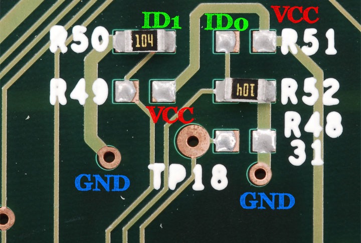
Table of states:
ID[1:0]
00 - Fluke 51 II mode
01 - Fluke 52 II mode
10 - Fluke 53 II mode
11 - Fluke 54 II mode
So firmware is same, and operation mode just selected on manufacturing phase, by soldering resistors on proper place. Cool!
To this time slamms provided me photo of his 54 II, so I continue.
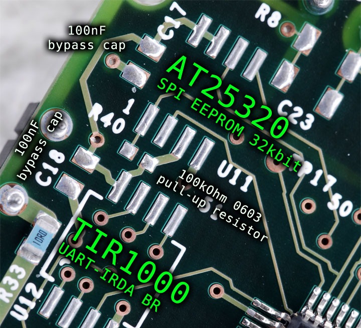
So this is what placed on 54 II as for logging features
I had no AT25320 chips that time, but we have SPI flash on any videocard
Googled a bit of datasheets, and get idea, that they are same pinouts, little different in command protocol. So....
Soldered Videobios from GeForce 7900GTX to my fluke 51-2 @ 54-2, added debug wires to USB-UART bridge, and tested link with PC


Some junk from bios chip read by fluke lol
notice 6K+ memory cell number. Native Fluke 54 support only 500

I drilled plastic case of meter and instert round rubber spacers for extra keys, as you see on photo. Need better rubber blocks to make "native-look" buttons


Terminal software from USB-UART bridge chip between fluke and my ws got data with 9600 8N1 port settings.

So now time to add second channel. Knowing already that Q1, Q3, Q2 and Q4 on top was MOSFETs in SOT-89 package i found datasheet on original DN2540 ones. These are depletion mode mosfets, in contra to wide-used enhanched mode mosfets found everywhere on motherboards and gfx. Difference was that these fets closed with negative gate voltage, not zero. I reverse engineered schematic of this part:
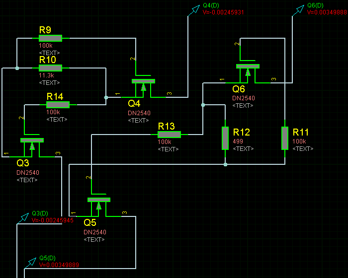
Simulated it with SPICE modeling, got nothing but voltage follower here. Correct me if I'm wrong
Looks like they used as buffers here, to isolate channels when they are not needed to avoid errors in readout.
I didnt found original fets where to buy, so decided to go with another depletion-mode mosfets with smaller SOT-23-3 package. They are BSS139.
So back to soldering now.
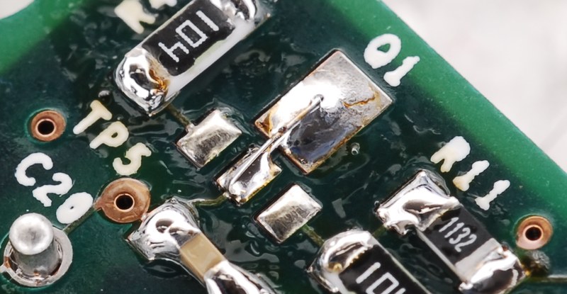
To solder SOT23-3 on SOT-89 pattern i used piece of wire to connect dummy collector pad to central pad.
So after 10 min i did my homework like this:
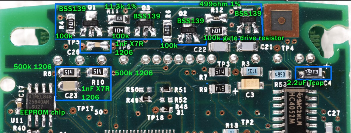
Get notice C4 cap on right - it's tantalum capacitor, beware right polarity (marked line is positive here). 2.2uF 6V or so fit nicely in SMA package.
R8 and R10 are just similar as R7 and R9, 500kohm 1206 resistors with 5% tol.
R4, R5, R6 and R17 are gate resistors, all 100kohm 1206 with 5% tol.
R11 and R12 are 1% resistors for thermocouple input, 11.3kohm and 499 ohm. Take care to make them best tolerance possible.
And most important part here - Capacitors C23 and C20. There affect precision and channel crosstalk very significant, I found best results with 1nF 0805 and 1206 5% capacitors. My bad I could not find NP0 capacitors now , but original fluke ones (C22 C21 eg.) are NP0. NP0 dielectric type have zero temperature drift and much more precise as in term of capacity to more cheapo X7R type. NP0's usually much more grayish and ligher color as for appearence.
This additions to board let me use second channel nicely.

Later I tried just shoring drain and source pads on Q1, Q2 Q3 and Q4 patterns, without soldering gate resistors and transistors - second channel worked this way too!.
Here's sketchy LED backlight with white 1206 SMD leds hanging on wires.

For graphing Fluke have FlukeView Forms 3.5 application, i found it on web before.
Pretty sure, i have it somewhere on my storage, if anyone need it.
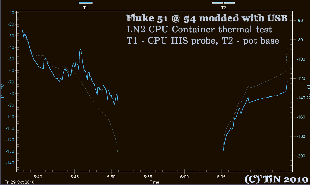
Testing datalogging.
CPU: Intel Celeron 356 at 6.5GHz with 1.92Vcc
Meter: Fluke 51 II modded, with two termocouples attached
T1 probe: mounted on edge of CPU IHS with grease and fixed tight by socket retention bracket.
T2 probe: mounted in copper container basement hole with grease
Logging interval betweek samples: 5 sec (can be any time down to 1sec).
LN2 pours at 5.41, 5.42, small pours till 5.50, then i meter off
then again log data from -190C.
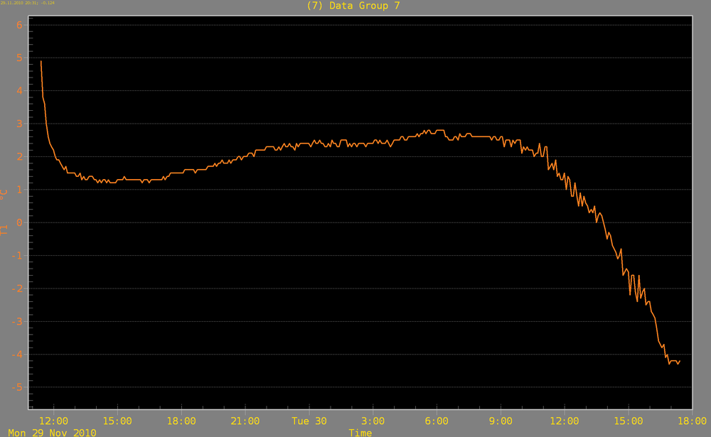
Another 5-min graph, ambient temp outside of balcony. It was winter
-----
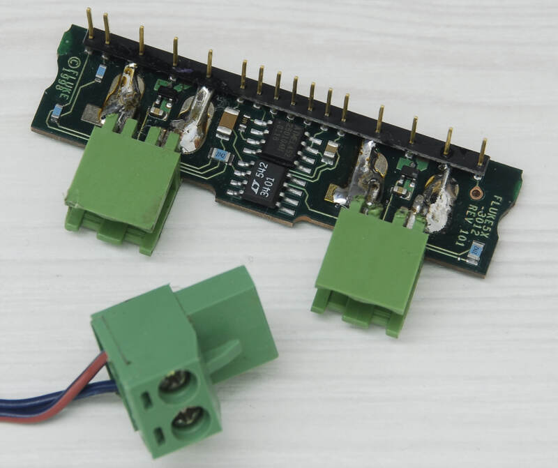
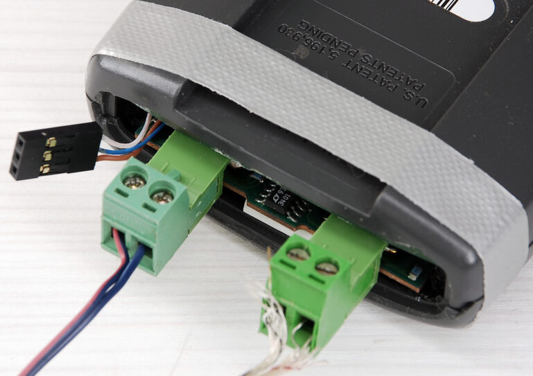
Also I did not like much spring type connectors on my fluke's, so modified one to
terminal blocks
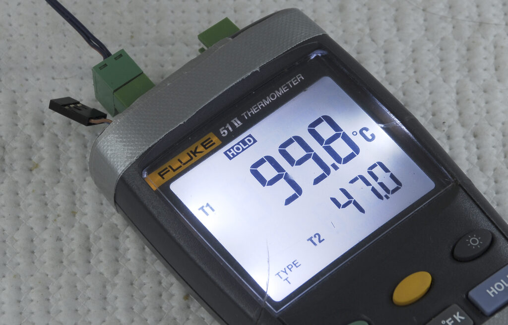
But of course accuracy went little bit off, as therminal blocks heavy and add thermal gradients
Hope you enjoy reading


