A quick follow up:
- I've been able to fix the -160MHz offset default setting
- I've been able to partially fix the 5 digits resolution default setting
- I've not yet been able to fix the sensitivity problem
For the default settings, I just replaced a few instructions in the initialization routine by NOPs, as described in
https://whatever.sdfa3.org/eip-545b-rf-frequency-counter-part-4.htmlThe problem with the resolution is that I do have all the digits displayed, but the actual resolution remains on 5 digits; I guess there is also some initialization code that configure the gate generator (A107) to modify accordingly...
For the sensitivity problem, I've not been able to put the YIG sphere in place: it is very hard to manipulate by hand. However, I a wondering if this is the only problem; I also suspect the 15dB boost in A201 to be faulty.
I've picked up the schematic of the A201 board (the IF amplifier/detector part):
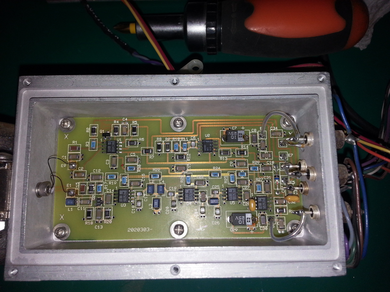

I've been suspecting the Q1 transistor, but I've been fooled by the fact it's a JFET, so it does measure low resistance between the source and the drain when the gate is not high.
I've desoldered it from the board, but it looks to work just fine (cheked with 20$ LCR/transistor meter).
On this schematics, I'm not sure what kind of signal is expected on input E9 (from the YIG): when measuring with a multimeter, I have very low resistance to the ground (maybe 0.2 or 0.3 ohm).
Looking at the output of the YIG, this E9 being the green wire, it looks to be, indeed, connected to the ground on the ceramic board:
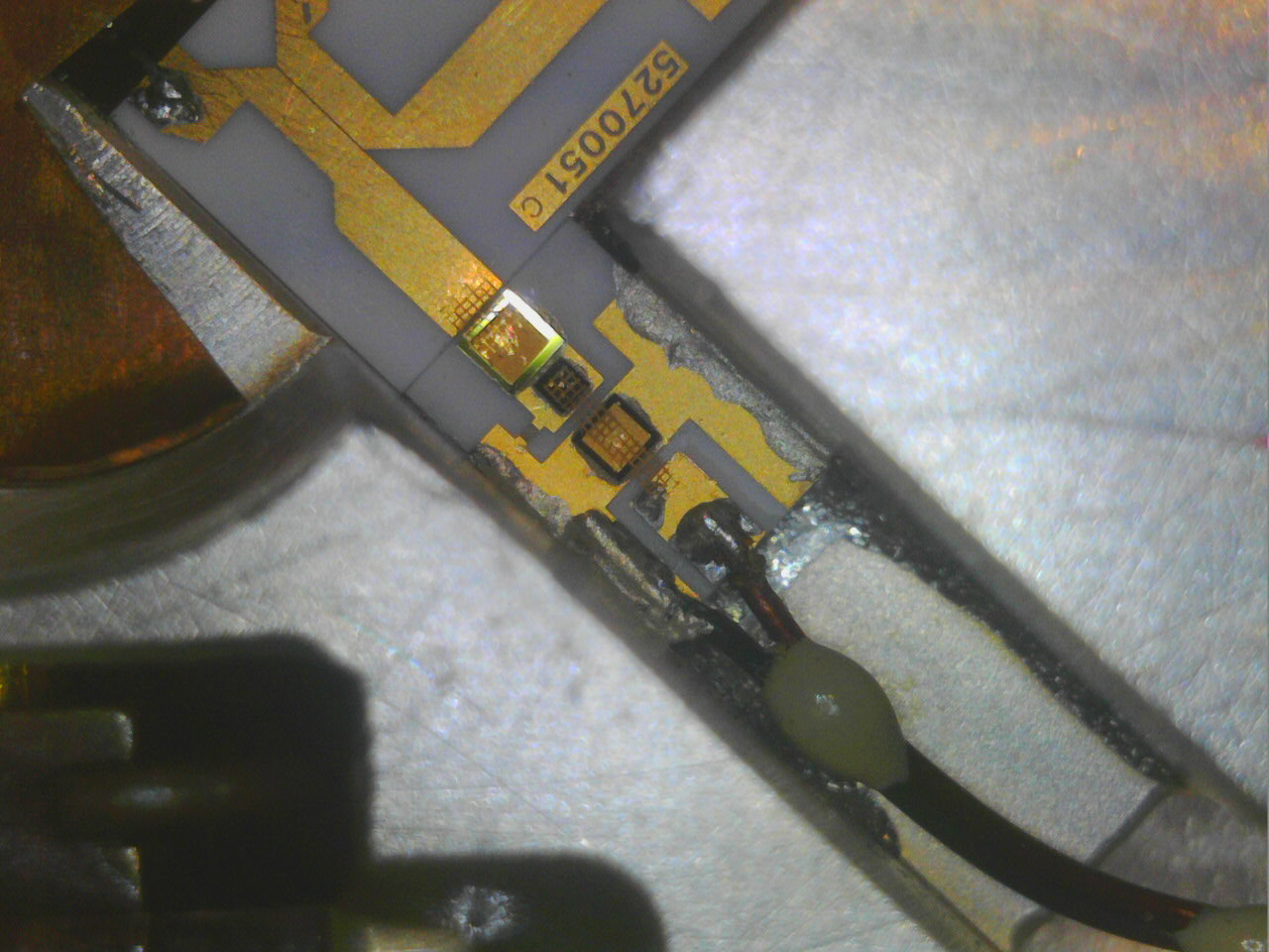
So I guess it should be considered as ground-level (once again, being a noob in RF, I've been fooled by the presence of R1/C1 there (especially R1), as both side of the wire are grounded, but as usual with RF, it's a "transmission line", not an equipotential, so I guess they make sense).
[edit]in fact, when Q1 is blocked, the gain of this amplifier is something like 32 (1+61.9/2), and when the Q1 is on, the gain drops to around 1, so the ~15dB boost controlled by the E7 input.[/edit]
So I need to dig more...
For those playing at home (as Dave would say), here is a picture of the whole ceramic board in the YIG enclosure, including the mixer (the IF signal generated by the VCO arrives on the pin at the top of the picture) :
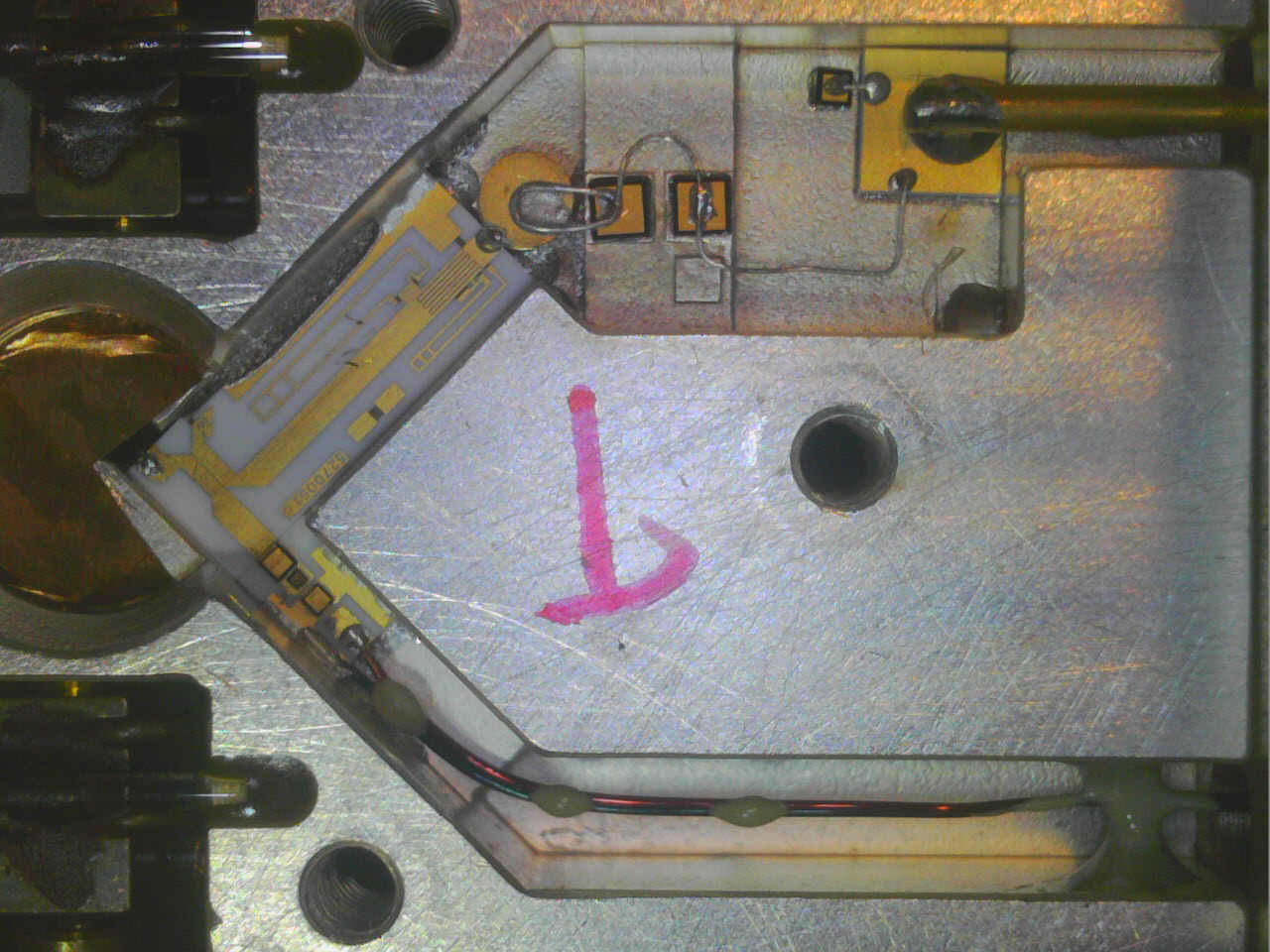
David


