Meanwhile I got a bit further.
I hooked up 3 power supplies to the power supply board to get the 5V, 12V, 15 and -15V rails going and another (big) one to pump some current through the DC Load. Ofcourse all power supplies are set to a very low current limit setting.
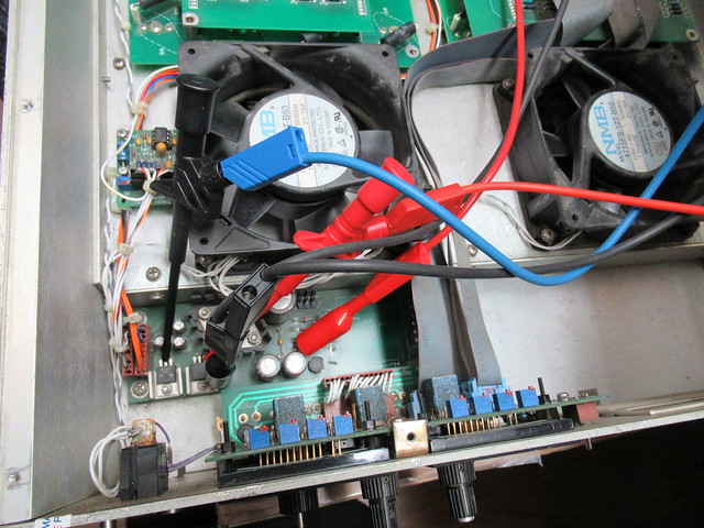
The displays worked but the +15V and -15V rails pulled a lot of current. Not good. After disconnecting the boards one by one it turned out the secondary regulator board had a short between +15V, -15V and ground. Interesting...
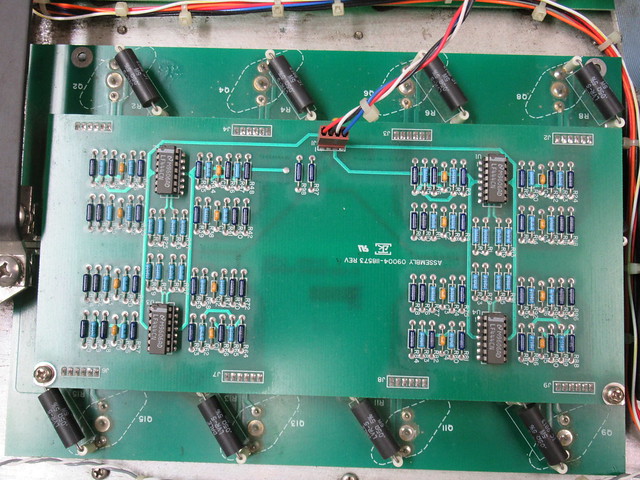
I checked all the chips but none of them where the cullprit. After pulling the secondary regulator board out it showed a bodge with two tantalum capacitors.
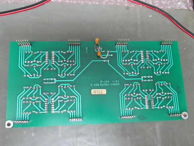
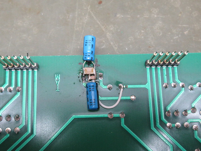
Both tantalum capacitors where a short (not a real surprise). I rebodged it with some electrolytics and 1nf ceramic capacitors.
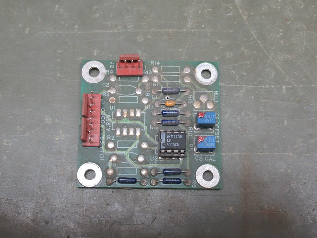
After that the DC load began to show signs of life. The voltage display showed about the right value however the current display didn't show the current through the shunt. I took the current sense board out, cleaned it and reseated the chip.
Before:
After:
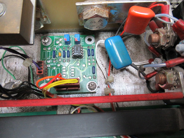
Cleaning and reseating seemed to do the trick because now the current display also works.

However still no go on controlling the current so I took the front panel out, cleaned it and reseated the chips.
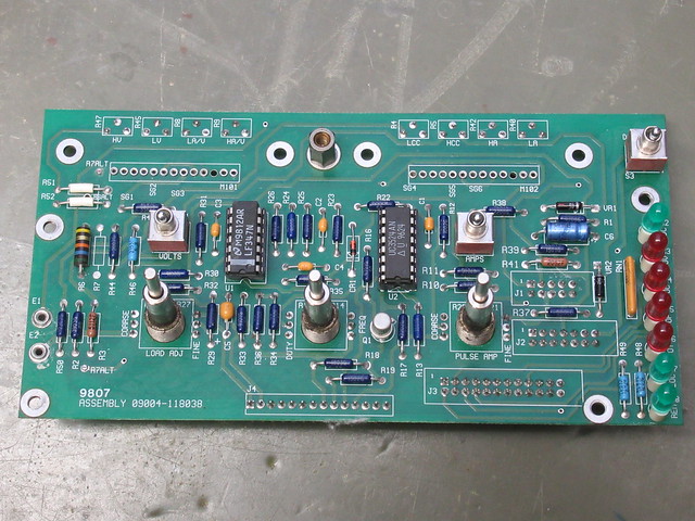
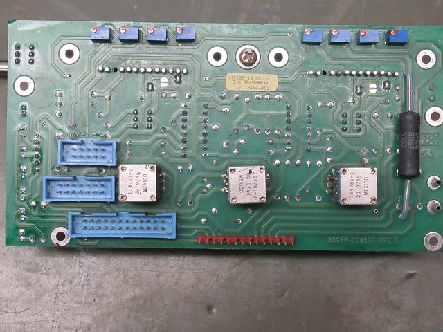
Since I was in the neighbourhood I also took the selector switch assembly out to check what was wrong with it. It turned out the latching plate which keeps the knobs in the selected position was bend upwards which allowed the notches on the buttons to slip under it. The construction is a bit flimsy. It would have been better if they made the latching plate into an L shape so it would stay straight.

After taking the switch apart, bending the latching plate back into shape and lubricating it with a bit of vaseline (acid free grease) it works like new but it won't surprise me if the problem comes back.

Time for a test so I put the selector switch and front panel back into the DC load. It works!!! I can set a current or constant resistance. However after a quick check I noticed I forgot to connect this little board:
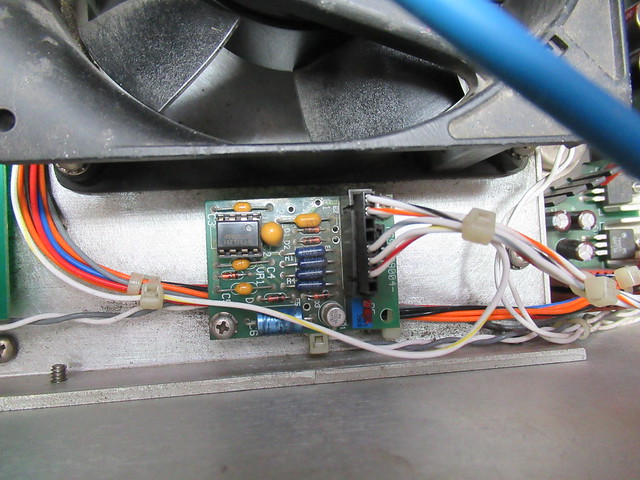
The service manual doesn't mention it so it's function is unclear. However after I connected it the DC load stopped working. I traced the wires back to where they are connected to. The wire going to the left goes to the main regulator board. All of the other wires are connected to the power supply. One of the wires goes to an PSU output with a rectified mains (100Hz pulse). This is a dead giveaway of what this board does: it is a power supply monitoring board! Since I'm powering the DC load using DC power supplies the 'mains present' signal is obviously missing and the DC load stays disabled.
Sit wrap: the DC load is working so I can go ahead with ordering replacement parts.
One of the decissions I had to make is about the power supply. I need to run the DC load from an 230V mains and I want to keep the 115V fans. I dug a little deeper into the power supply circuit.
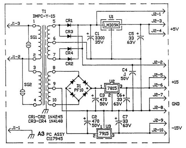

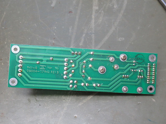
What bothers me is that the clearance on the board is marginal at best. Maybe OK for 115VAC but not for 230VAC. The designer put in solder bridges (left top part of the PCB) to select between 115VAC or 230VAC but the bridge required for 230V is covered in solder mask. And then there is also the small gap between the pads of the primary and secondary windings. I don't want 230VAC on this board! Hell no!
This left me with the following choices:
1) Design a new PSU board (which is quite a bit of work).
2) Buy one or two chassis mount transformers and solder the outputs into the existing PSU board.
3) Modify the existing PSU board to have isolation slots.
4) Put the original transformer in and add an (internal) step-down transformer to convert 230VAC to 115VAC
After thinking about it for a while I choose to go for option 4. Option 1 is too much work, option 2 looks shoddy and option 3 requires some very carefull milling and I'm still not happy with the clearance on the mains connector. Also the use of a step-down transformer allows to rewire the unit for 115VAC if needed.
With that decission made I could order a whole load of stuff from Mouser: a mains transformer, step down transformer, mains switch, 10 turn pot + knob, 6AWG (13mm^2) lugs to connect wires to the bolts at the back and parts for the fan control board. I'm not going to change the flatcables. Although they are dirty they seem to work fine and the wires are actually used in pairs for each signal. The designer probably wanted to add extra reliability.
The thing I'm still contemplating is whether or not to add fuses to the secondary side of the mains transformer. I can imagine the original transformer overheated and failed due to the short.
To be continued...