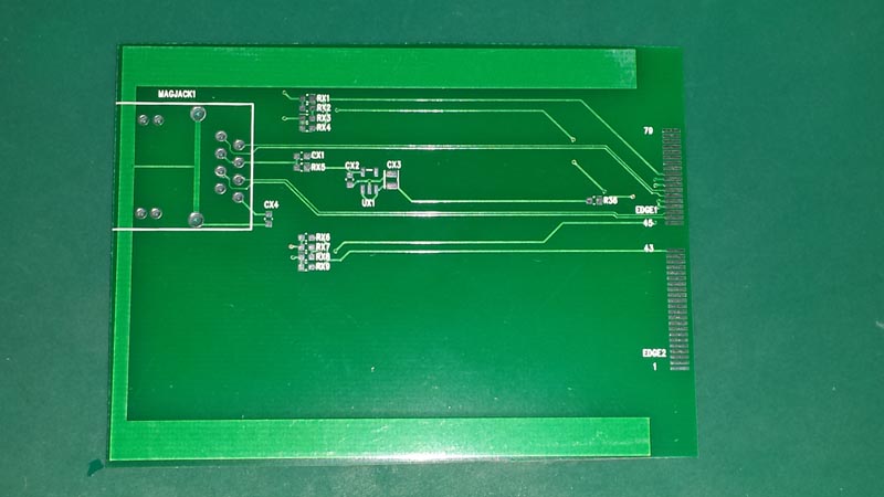
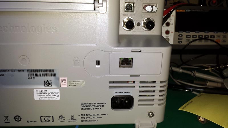
So, I have my LAN board working nicely thanks to Zucca's clarifications of some of the signals. I'll post up a schematic in the next day or three, but here's some pics.
First pic is my lan board (most of the resistor options etc are to cover any cathode/anode polarity issues with the LEDs - before Zucca provided the additional details, and if a regulator would be needed for the termination network in the magjack). This is a picture prior to cutting out a slot in the edge connector and trimming the excess board material. This PCB was on a 'panel', so it was cut from a large rectangular panel of various other test boards etc.
After trimming it was a perfect fit into the edge connector in my dsox scope.

I carefully measured the length of the board so that it would fit snugly into the pocket with the plan to cut a hole for the magjack to stick out. By choosing the length 'just right' the original plastic clip/panel snaps nicely into place and supports the magjack end of the board and prevents it moving in any direction. Worked out nearly factory


LEDs work, board works and I can access it via the webpage for full control. I used telnet to update the 2 required files that open up the licenses inside the scope. This halves the boot time (compared to the USB drive) but more importantly allows the webpage access to work. As someone else in this thread found, if you boot from a USB drive the webpage stuff doesn't work and reports an error.
Of course (as per the other DIY lan boards), the scope doesn't recognise it, so it doesn't appear in the utility->I/O menu, but all the configuration stuff can be done via the webpage server. In my case I put it at a static IP (starts off working since it gets an IP from a DHCP service on the network.
cheers,
george.