I did some tests with the detector I made using the HSMS-286B. I used an SMA connector with four 200 Ohm resistors to form a 50 Ohm termination, the HSMS-286 diode, a 47nf capacitor and a piece of copper clad to keep everything together:

The capacitor is hard to spot but it is at the bottom right leg of the SMA connector:

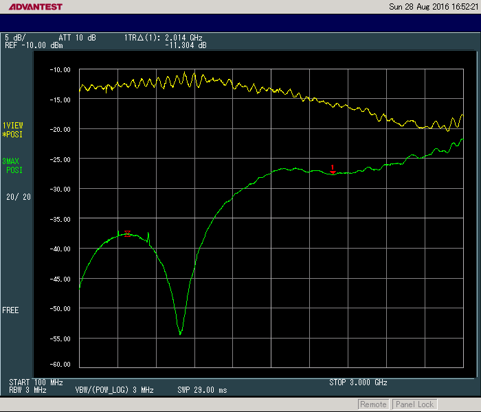
I measured the return loss up to 3GHz but the directional coupler I have (Mini-circuits ZFDC-10-5-S+) is specified for use up to 2GHz. The yellow trace is the open load situation, the green trace with the detector connected. At 2GHz the VSWR is around 1.8 (if I calculated that correctly from the 11dB difference between the traces at 2GHz).
I also did some measurements at various levels. For these tests I connected the trigger out from my RF generator to the trigger input on my Keysight 34461A. This way the measurment is done automatically because the generator sends a trigger pulse for each step it makes until the sweep is finished. The sweep is from 100MHz to 3GHz so each division is 290MHz.
0dBm input:

-6dBm:
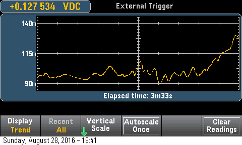
-20dBm:

All in all the level appears to be flat within 1dB up to 2.7GHz at various power levels. After that something is going on and this may be caused by to poor impedance matching due to the capacitance of the detector diode.


