My lab has a few different generations of Yokogawa power meters, and I thought I'd compare the internals side-by-side. All of them accurately measure power (AC and DC) by quickly sampling voltage and current, and doing digital processing (mainly multiplying I*V, then integrating to get an average power). They can also do more complicated things like calculate reactive power, power factor, etc. These types of instruments are essential for accurately measuring AC power, and can be useful even for DC power too (at the point where the accuracy of the "two Flukes, one for current and one for voltage" method isn't enough).
The first we'll look at is also the newest one, which is a self-contained single-channel model, the
WT210.


The inside is pretty easy to figure out in a general sense:

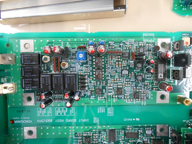
At the left, just behind the front-panel display/button board, is the power supply. The top half of the main board is the digital processing and external comms, while the bottom half of the main board holds the isolated voltage (left) and current (right) measurement sections. There was originally a metal shield over the voltage-sense section, just like over the current-sense, but I removed it before this shot.
Since the voltage and current-sense sections have to be isolated from each other/everything else, you can see the row of optocouplers down the middle for carrying ranging signals and measurement data back and forth to the digital section.

There's also an isolated power supply for each sense section: you can see the transformers on the top-side of the board...

...the dual transistors on the bottom whose connections show that this is probably a resonant push-pull/"Royer oscillator" converter...

...and some filters and linear regulators to clean up the outputs:

Here's a close-up of the voltage-sense section:

The big chip on the left is an obscure
Asahi Kasei AK9216-VS 16-bit 100 ksps ADC. The rest are digital logic, op-amps, or analog switches, presumably for voltage scaling and ranging. Notice the big voltage-divider resistor ladder on the right for scaling down the input voltage. There's 20x 100K resistors here, for 2M total.
The bottom side doesn't have a lot going on. Interestingly enough, though, it looks like the top side was reflowed, while the bottom side got wave-soldered (notice the large "capture pads" on the corners of the chip).

Given this, it also makes sense that the fine-pitch high-pin-count chips in the digital section are all on the top side, as we'll see later.
Current sense section next: the current-sense terminals are protected from too-large voltages by a pair of really beefy-looking TVS diodes:

From there, they run to a set of flat busbars on the bottom side...

...which mostly seem to route the power around a couple ranging relays and the current-sense resistors themselves, sandwiched between heatsinks:

As there's two resistors visible, maybe the relays select parallel/series/individual combos of the resistors for different current ranges.
The rest of the current sense section looks mostly like the voltage sense section, minus the voltage-sense resistor ladder:

There's the same ADC on the left, and a similar arrangment of analog switches and op-amps. There's also two resistor arrays visible here, as the black vertical rectangles: this are probably thin-film resistor arrays deposited on a ceramic base; you can get these laser-trimmed with tight tolerances on the relative ratios, and good matching over temperature changes...overall, exactly the kind of thing you'd want for pairs of op-amp feedback resistors in an instrument that needs to keep a high accuracy.
The digital section has a whole lot of discrete logic chips scattered around, much of it flip-flops and buffers (I'd assume glue logic between all the different processors, memory, peripherals, etc.):

There's a mystery Yokogawa-branded chip at the bottom-left and a Renesas SH7021 RISC CPU at the top-left, probably for general control. Underneath the upside-down extra card on top, an Analog Devices SHARC DSP and oscillator peek out:

This is almost definitely what handles all the multiply/accumulate action for power calculations (and RMS, real/reactive, power factor, crest factor, etc.).
Adjacent to all that is some memories: a couple Renesas R1LP0108 128Kx8 SRAMs, and what look like socketed ROMs with the firmware.

Towards the back panel is an unpopulated section which lines up nicely with the covered-over GPIB slot on the back panel:

I like the legend showing which groups of components get populated for which models.
Finally, I'm a fan of the mounting style for the main board, seen most easily from the bottom side:

Rather than having long standoffs running down to the bottom of the chassis and needing embedded PEM nuts or extra screws down there, instead they form tabs from the sides of the sheet-metal chassis by cutting around 3 of the 4 sides, bend them over horizontally, then drill and tap them. Seems like if you're making cuts and bends in the sheet metal anyways for vents and overall forming then you're halfway there already.
Next, let's look at the
WT1010.

This one's larger, but not just because it's older; it has a modular style, where you can add voltage-and-current-sense modules as needed to form a multi-phase system. In this way, you can scale it from single-phase AC/DC power to 3-phase AC power just by buying more modules.

Here's one of the modules, which unsurprisingly doesn't look all that different from the measurement section of the WT210:

The voltage sense...

...and the current sense...

...look really similar to before, except that there's more DIP packages hanging around. ADCs are on the left in both cases (now the
AK9202, looks the same as the AK9216 but in a different package), and optocouplers for digital comms are in a row along the bottom.
The current sense resistors have a bigger heatsink than before:

Other notable points include...
The now-off-board isolated power supply for voltage- and current-sense:

The DSP board mounted to the backplane:

Mysterious labels for unpopulated expansion cards, "motor" and "waveform"...no idea what those might do:

A floppy drive!

Enough of that power meter. Now on to the
PZ4000, which has a similar modular multi-phase setup as the WT1010, but which I think may be older, despite its large graphical LCD:

I had trouble getting the cover off, but the single installed module conveniently comes out of the chassis without opening the whole instrument!

The back of the module has some connectors for power and data to the backplane, and also some spring-contacts for connecting the module's shield to the whole instrument's shield:

Not sure who opened this before me, but the calibration sticker honestly was already broken, ok?

This module's bigger than the last one. At the right side, after taking off the plastic side covers, you can see the isolated DC-DC supplies for the measurement sections, installed on risers:


Under each of the DC-DC cards, the optocoupler party is going on:

The view with the shields removed:


There's an angle bracket at the back end, holding a board at a right angle to the main one, which hosts the voltage and current sense connections:


That's a nice 4-terminal (Kelvin sense connections) current-sense resistor there. Looks like it's heatsinked to some heavy metal brackets underneath.
The current sense section doesn't have anything exotic, although there are a bunch of relays at the front-end, even more resistor arrays than before, and the ADC is an Analog Devices AD9220, which is a 12-bit 10Msps part. Looks like this one has lost a bit of resolution compared to the others, but traded it off for a much higher speed! Maybe the PZ4000 was sold specifically as a high-sampling-rate power meter? It would make sense to have a higher-bandwidth version for things like aircraft power (400 Hz), or power systems with a lot of energy in the harmonics. For all I know, this power meter may even do some spectral analysis on the input power and show the harmonic levels directly.
The voltage sense has an interesting piece. First, the overview:

Now, let's zoom in on the big almost-definitely-high-side-of-a-voltage-divider resistor at the left:

That looks like a capacitor, formed with parallel copper areas on a PCB, connected in parallel with the sense resistor to flatten its frequency response! Doing this with a PCB might seem strange, but I can see some situations where it makes sense. Here, specifically, you have the combination of...
1. High-voltage insulation. High-voltage capacitors can be expensive or have limited selection, while standard FR-4 has a high insulation rating: put two plates on opposite sides of a 1.6mm piece, and you've got at least a couple kV.
2. Custom, small capacitances. Small capacitances are hard to find and usually have large tolerances. It gets to be even more of a pain if you need to shim a bunch of standard-value ones in series and parallel to get the right capacitance anyways. Here, you can get exactly what you want by changing the plate sizing. The Yokogawa engineers probably made a bunch of these capacitor boards with a range of plate sizes so that they could swap them in and out easily.
So that's all, nothing wild or completely unexpected in these but still interesting to see what goes in inside a digital power meter.


