Author Topic: Yokogawa DL1740 oscilloscope repair & teardown  (Read 8884 times)

0 Members and 1 Guest are viewing this topic.

Online nctnicoTopic starter

  • Super Contributor
  • ***
  • Posts: 27384
  • Country: nl
    • NCT Developments
Yokogawa DL1740 oscilloscope repair & teardown
« on: September 04, 2015, 11:18:45 pm »
I have been looking for a small form factor oscilloscope for a while to use as a spare oscilloscope and to bring along to customers. I could have gotten a Rigol 1000Z or something like that but I wanted something which packed a bigger punch. I had spotted a Yokogawa DL1740 (4 channels 500MHz) with two defective channels (1 and 4) on Ebay but as usual the seller wanted too much money. A couple of weeks of patience paid off because he dropped the price down to $300 and decided to put it up for auction. At that point I decided to take a stab at it even though the price was still too high but sometimes it happens an item sells for more than the previous price after a price drop.

The reason I picked this oscilloscope is because it also has the LAN connection option, reasonable long memory (up to 1Mpts), a color TFT screen and PC software which is still being maintained by Yokogawa (the latest version is only a few months old). This oscilloscope also has some nifty features like sending a screendump to an FTP server after each trigger and/or sending an e-mail. I get the impression that the oscilloscopes from Yokogawa are also geared towards long term monitoring of signals.

When I unpacked it I was surprised to find it also has a pouch for probes and maybe a mains lead. Some photos of the case:

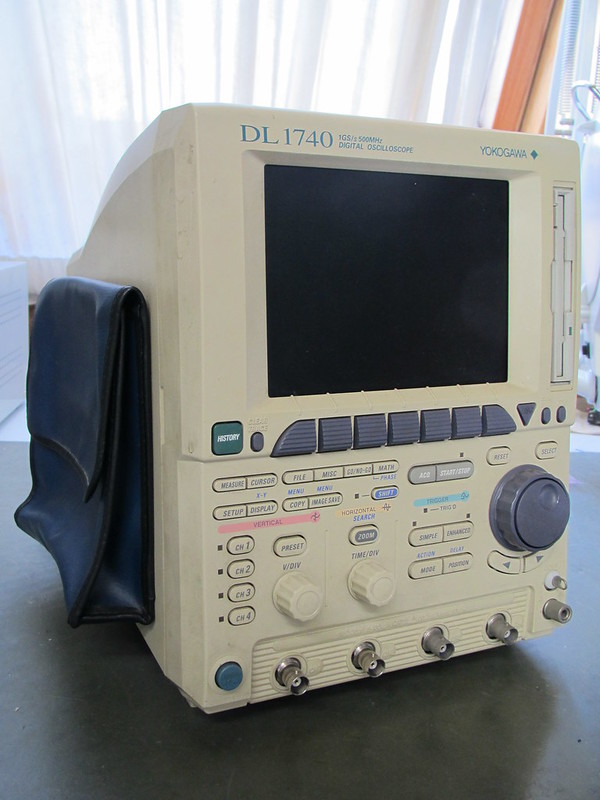
The oscilloscope says 1Gs/s on the front but that is only in half channel mode where channel 1 & 3 use two (interleaved) ADC converters. However, it can also do equivalent time sampling so it is not entirely useless for measuring 500MHz signals. Oh... and how cute is that pouch on the side? I think I'll nickname it Aussie...


It is almost typical for Japanese equipment to get so discoloured over the years. The contrast between the disk drive and the case makes it painfully visible. The blue parts turned into some teint of purple.

It does have this nasty error message due to two channels not working:


Time to take it apart. Fortunately I managed to buy a service manual for this oscilloscope from Ebay for a few euro. That has a block diagram of the circuitry (of course no schematics) and the way to take it apart which isn't straight forward with a compact unit like this oscilloscope.

The front:


CPU board (note the buzzer glued to the large chip in the middle!):

The CPU board has an ethernet daughterboard attached to it. Judging from the amount of memory I guess the ethernet board does all the heavy network lifting by itself. The extra slot is for a SCSI + serial port interface option I don't have. The SCSI interface allows to connect an externel SCSI hard drive for storage. At the bottom right there is a connector for a floppy drive or a ZIP drive. I have not investigated the ZIP drive connector in much detail but it may be an IDE/PATA compatible interface. From the traces on the CPU board it may be connected to the data bus.

I wanted to push on to the pressing matter of the two channels not working so I focussed on the acquisition system. The acquisition system consists of two board piggy backed together. On the opposite side of the acquisition board is the digital data handling & storage board:

This is where the data from the ADCs is stored into SRAM (left part of the board). The signal post processing happens on the right side of this board. The DRAM is used to store previous acquisitions. This oscilloscope does not use segmented memory (it could have) but uses extra memory to store previous acquisition which can be recalled using a history button. Last but not least the section which drive the display is also on this board which is why the VGA output connector is also on this board.

The acquisition board:

The 4 ADCs in large QFP packages are easy to spot on the right. The smaller chips are the trigger comparators. Fortunately the attenuator and pre-amplifiers are in two seperate modules providing two channels each. Swapping the attenuator/pre-amplifier modules quickly showed that the primary problem is not in the main board but in the modules. The ADCs all work and offset controls also work. Because the calibration is off it is hard to determine what is causing which problem. With the modules swapped is was very hard to make the oscilloscope trigger so I decided to dig deeper into the acquisition board to make sure it worked OK. One thing I was missing where DACs to make the various DC control voltages. It turns out the big QFP chip in the middle is generating PWM signals which are then filtered using RC filters and made bipolar using opamps. One of the interesting discoveries I made has to do with the offset. The oscilloscope has two signal offset controls. One adjusts the offset in screen divisions and the other in Volts. Both offsets adjust the same control voltage!  :palm:  Anyway, when I swapped the modules back to their original position triggering worked again.

The attenuator/pre-amplifier module front and rear:


Besides the relays there are three chips. The one in the middle is a mux which switched between normal and interleaved mode. The pre-amplifiers are under a lump of heat conductive silicone rubber. The pre-amplifier chips do a lot: amplify the signal, bandwidth filtering, prepare the trigger signal + offset, apply DC offset and output a differential signal towards the mux. Yes they get very hot! After some probing and testing it turns out two channels not working is caused by the pre-amplifier chips. Bummer because they are made by Yokogawa. Oh crap  :'(

Sitrap: I have two working channels, one is flaky (unstable) and one is not working at all.

OK. A two channel 500MHz scope for $400 ($300 + $100 for shipping) ain't bad but it would be nice if I could make channel 1 & 3 work so I could use the interleave mode. So I decided to get my hot-air station and swap the pre-amplifier chips. I decided to leave the completely dead one out (less heat) but keep the flaky one just in case it could be useful.

More bad news:

It turns out I'm not the first one swapping these chips! The signs of a replacing a chip gone wrong. This damage typically comes from whiping the pads with solder wick. I used to do that too but I found out it is much better not to try and remove the old solder. Instead I remove any flux residues using ethanol or flux-off, apply fresh flux and just reflow the chip in place. After that some touching up is enough to make it perfect.

I think one of the root causes is that the attenuator/pre-amplifier modules get no airflow at all so I'll drill some holes in the plastic outer shell to leave air in at the attenuator/ pre-amplifier modules. I did manage to track down a Chinese chip broker who claims to have the pre-amplifier chips for sale. Their price is reasonable so I'm going to try and order 4. Knock on wood! One of the less pleasant things about the DL1740 is the noise from the fan. It's not very quiet and it doesn't have much openings to let air in (two to be precise: at the top where the printer is and at the bottom where the ADCs are) so the fan is not moving much air.

On to playing a bit with my 'new' scope...
One of the things I wanted to try is FTP access. Setting up an IP worked after a reboot of the scope. After that I can access the floppy drive from my browser and download images. Added bonus: I now have a network attached disk drive so I can read disks from my PC again!


From the last picture it seems it also has some form of intensity grading. So far most of the operations have been straightforward (didn't need the manual) but there are some differences. Japanese oscilloscope makers have a habit of calling peak-detect 'envelope mode' and on the DL1740 you won't find an FFT math operation. It is called PS (power spectrum) instead.

edit: typos
« Last Edit: September 05, 2015, 03:20:58 pm by nctnico »
There are small lies, big lies and then there is what is on the screen of your oscilloscope.
 

Offline marshallh

  • Supporter
  • ****
  • Posts: 1462
  • Country: us
    • retroactive
Re: Yokogawa DL1740 oscilloscope repair & teardown
« Reply #1 on: September 05, 2015, 02:21:59 am »
That thing is so japanese it hurts.  8)

I'm fairly sure most of those asics are NEC-fabbed gate arrays. Except the ADCs, couldn't make out enough of the lasering on those.
Verilog tips
BGA soldering intro

11:37 <@ktemkin> c4757p: marshall has transcended communications media
11:37 <@ktemkin> He speaks protocols directly.
 

Online nctnicoTopic starter

  • Super Contributor
  • ***
  • Posts: 27384
  • Country: nl
    • NCT Developments
Re: Yokogawa DL1740 oscilloscope repair & teardown
« Reply #2 on: September 22, 2015, 05:16:25 pm »
Look what arrived in the mail today.. 4 brand new Yokogawa L6294LG pre-amplifier chips! They look brand new and where very well packed!

I decided to replace the chips without taking the analog board from the scope and leave the attenuator modules in place as well. The chips are easy to remove and easy to place with a hot air station. A neat trick when using the reflow method is that a few gentle taps on the board make the solder pull the chip into place perfectly! After turning the scope on with some test signals applied:


Tadaaaaa! 4 working channels and the message that the self cal couldn't be completed is gone. Only channel 2 seems to have a problem with one of the databits of the A/D converter. So almost 4 working channels. And now the scope complains the CMOS battery is low at startup :palm: -sigh-

I ordered the pre-amplifier chips from www.jotrin.com in Hong Kong. Given all the stories about fake/used chips from China I wasn't really sure I would receive the right chips but it seems Jotrin can be trusted. They even put the VAT number on the envelope so customs processing went quickly. Thank you miss Fang!
« Last Edit: September 22, 2015, 06:54:11 pm by nctnico »
There are small lies, big lies and then there is what is on the screen of your oscilloscope.
 

Online nctnicoTopic starter

  • Super Contributor
  • ***
  • Posts: 27384
  • Country: nl
    • NCT Developments
Re: Yokogawa DL1740 oscilloscope repair & teardown
« Reply #3 on: September 22, 2015, 10:57:53 pm »
As an extra treat a color graded image from an FM modulated signal:
There are small lies, big lies and then there is what is on the screen of your oscilloscope.
 

Offline dzseki

  • Frequent Contributor
  • **
  • Posts: 521
  • Country: hu
Re: Yokogawa DL1740 oscilloscope repair & teardown
« Reply #4 on: June 10, 2016, 08:46:09 pm »
This thread made me buy a DL1740 with the same error message.
While the problem was the same as with Nico's, but I was less fortunate, because my input IC got badly burned:

The degree of burning in such sensitive circuit made some doubts in me if it is possible to repair at all. Normally I wouldn't even bother with repairing that channel, but because the self cal could not run the trigger offsets were way off, so practically the internal triggering did not work at all. Anyway even removing the old chip was a nightmare even with a hot air station, there were a lot of pads that were damaged or completely destroyed. Fortunately while this IC is in QFP64 package, only a dozen legs are actually used in total.
So I got the replacement ICs from Jotrin, and could replace the IC yesterday. It was a delicate work, with a hand soldering iron, I also had to replace a few burnt up traces and so on, I did not even expect good performance from that channel, but as later turned out it is worked as it should. A screenshot starring with the repaired channel:

670ps rise time, not bad...
The scope went several hours yesterday with on off cycles too.
I was so happy... until today. I switched on to play a bit more with the new toy, but this time I barely got through the welcome screen, then all LED start to blink on-off just like the cooling fan, then came the smell of burnt electronics... I had a faint idea where to look LOL, but I was pretty surprized to find that now CH3's preamplifier IC is died (that was worked before), and by the look of it, died in a very similar way how I got CH1. This is CH3 how it looks:

Fortunately the PCB damage is rather small this time, those burned legs by the way are the +/-5V supply lines, and by the look of the bulging of the chip package looks like as if the chp would became shorted inside.
What is also strange the chip died almost instantly after powering up, so it is certainly not an over heating issue.
There are thick rubber(silicon) pads attached to the top of these chips to help heat transfer towards the case, these pads on mine are sweating out some grease too, but as I check with my multimeter it is not conducting.
Maybe a voltage peak during power on kills it? However there is a fair ammount of other parts in there those are fed from the +/-5V line.
To follow this trail I looked quickly on the power supply (it is a switching PSU), the +5V (to be exact +5.2V) line is driven by a PQ31RV31 linear series regulator so I'd think this should be stable, while as I could see the -5V line is not regulated by a series regulator, only controlled by the feedback loop of the PSU, so here I can imagine a voltage spike...
The next step will be (after replacing the dead IC) to install 5.1V zeners close to each preamp ICs power pins.


HP 1720A scope with HP 1120A probe, EMG 12563 pulse generator, EMG 1257 function generator, EMG 1172B signal generator, MEV TR-1660C bench multimeter
 

Offline tautech

  • Super Contributor
  • ***
  • Posts: 28937
  • Country: nz
  • Taupaki Technologies Ltd. Siglent Distributor NZ.
    • Taupaki Technologies Ltd.
Re: Yokogawa DL1740 oscilloscope repair & teardown
« Reply #5 on: June 10, 2016, 10:41:29 pm »
This thread made me buy a DL1740 with the same error message........

To follow this trail I looked quickly on the power supply (it is a switching PSU), the +5V (to be exact +5.2V) line is driven by a PQ31RV31 linear series regulator so I'd think this should be stable, while as I could see the -5V line is not regulated by a series regulator, only controlled by the feedback loop of the PSU, so here I can imagine a voltage spike...
The next step will be (after replacing the dead IC) to install 5.1V zeners close to each preamp ICs power pins.
Have you checked the secondary side caps.....they should be low ESR units and if tired could be responsible for high ripple that could make IC's do all sorts of silly things.  :scared:

That's what I would check first.
Avid Rabid Hobbyist.
Siglent Youtube channel: https://www.youtube.com/@SiglentVideo/videos
 

Offline dzseki

  • Frequent Contributor
  • **
  • Posts: 521
  • Country: hu
Re: Yokogawa DL1740 oscilloscope repair & teardown
« Reply #6 on: June 11, 2016, 02:05:12 pm »
OK, an interesting update.
I've spent a lot of time with checking the PSU behavior, but could not find anything noteworthy. I did not feel like removing the bad IC yet, instead I cut the burnt power supply legs to eliminate the short. During power supply testing I put back the analog assemblies to see how the lines behave with normal load, and one thing that was interesting the scope booted up without an error message, then I tested and in fact even Channel 3 is working despite the burn out! How is this possible? The preamp IC has power supply legs on two sides of the package and as it seems they are identical.
So now it is more confusional what happened with it? The grease-sweat of the silicon pad is the first thing that comes into my mind again, but then the IC package would not bulge from inside. Perhaps the bond wires within the package can't stand the inrush current of the chip, and acting as a fuse, and accidentally cause an internal short? If this is the case then CH3's preamp ic has its days counted since it is already running on half supply legs count... To support this theory it is interesting that there are no series resistors throughout the supply line (not one I've seen at least), so basically the +/-5V from the PSU reaches this preamp IC with "zero" resistance (not counting the losses of the PCB tracks and connectors) this I find rather strange.
HP 1720A scope with HP 1120A probe, EMG 12563 pulse generator, EMG 1257 function generator, EMG 1172B signal generator, MEV TR-1660C bench multimeter
 
The following users thanked this post: shakalnokturn


Share me

Digg  Facebook  SlashDot  Delicious  Technorati  Twitter  Google  Yahoo
Smf