-
Congrats on the good price on the eBay item.
Nice. Those are great insights, I wasn't entirely clear on the meanders nor the 6 MOSFETS.
Volt adjust is fairly straightforward. The cal information and software can be downloaded from Array's website. The software is not well made and unreliable for controlling the device but its fine for data collection.
But if anyone can write a better version! I'd be happy to test it out
Note the reverse input protection causes non-stop beeps and a warning on the LCD but it shorts the load rather than cuts it out, so it will draw the full output. It'll be a shocker if you were testing high current DUT and had reversed the leads in error.Yep. Me. Snatched it for less than that

I have some 'reverse engineering ' info.
The meanders on the pcb are there for a purpose. The two powerfets at the back have their own 0.1 ohm sense resistor to close the loop. These two resistors share a single trace on the board that is via-stitched between top and bottom layer and comes to the front of the board. The meanders on the front resistors inject the same trace length to the star point. The reason is load balancing. The pcb trace resistance would be different between front and back and the front fets woul pull more current than the back. Deliberate operation. Good design.
The bank of 6 mosfets on the main board is for range switching.
The use either 0.2 ohms for current measuring , in series with 0.02 ohms ( five 0.1 in parallel ). At high current they turn on the bank of six mosfets to short the 0.2 ohms out.
A relay toggles between the sense points. ( strange.. No analog mux ... Probably because there is a post divider protecting against large voltages.. )
My machine is off in the voltage measuring department. The programmed and measured currents are correct. The voltage measured on the terminals is wrong , so it probably needs adjustment.
The sticker said. Cannot adjust , but they didnt even try.... None of the pot seals are broken and this machine has no electronic calibration.... Lazy callabs... -
Good ! got the info. will hook it to the calibrator over the weekend.
I download the software.... typical national instruments tripe ... made in CrapWindows or Crapview..
I'll write my own. Just need to find the comms adapter .... -
I've completed the functional testing. In a nutshell, I ran 90W for >1 hour and checked the response of the electronics, the load distribution between the modules, and the stability of the readings. During that time I ran all the modes, CC, CR, and CP but kept to about 90W or more. I programmed a series of variable loads, going from 0.01A to 2.5A and various level between and ran for 30 min. Temp was measured with an IR thermometer.
Loads on the power MOSFETs appeared evenly distributed as measured through its voltage across load resistors
the Array can slew far more ~> 1A/1mS as measured to the response to variable loading
The unit held its calibration as monitored by Fluke 87Vs checking current and voltages
The fans are a soft hum and not a harsh blowing whine when at full power
The fans engaged at 40C, and keep the unit at a constant 38C. It shuts off at 35C, the difference being as thermostat hysteresis. Each load module was only1C warmer at the center of the heat sink compared to the end, and -4C at the exhaust end of the vents.
The dual supply linear regulator ICs warm up to4050C, while the 5V supply peaks at 64C
The most annoying drawback is the voltage drop across the hook up cables so one will have to compensate for it
The interface is fairly simple, and direct. Rare glitches happened when playing with button and rotary control adjusts, the system would then jump to init mode, which happens quickly so its not a bother, 1 sec or less. All the saved defaults remain untouched.
-
Good info thanks saturation, so the question still begs ... Maynuo M9712 OR Array 3711A
Both are around the same prices with the Maynuo being newer but the maynuo is only 150V and has battery test feature (Of course my prices are quoted from china directly)
Forget about the CA5030 from precisegauge, i can get a 3711A cheaper than the CA5030 -
Instead of one 3711A I bought two 3710A devices. They can be parallelled to handle more load or put in series for a higher voltage or used for two different projects at the same time.
-
I'm still thinking whether the battery test function is worth the extra dollars ...
Instead of one 3711A I bought two 3710A devices. They can be parallelled to handle more load or put in series for a higher voltage or used for two different projects at the same time.
Sure but they aren't exactly light or half the price in any way so i'd get a single 300W unit plus shipping's not free. so yeah (40-50bucks for 4.5kg) -
T4P, i should declare "an interest" first - I've just bought a Maynuo M9712B! (300W, 500V 15A)
In looking at the Array equivalent, a few points.
The Maynuo specs quote almost an order of magnitude better basic accuracy (Maynuo 0.03%+0.05%FS Vs Array 4.00~35.99V?0.2%+30mV )
The Array generally resolves to three decimal places (1ma, 1mV) while the Maynuo stretches to four for voltage (0.1mV) and five for current (10uA!!), BUT that last current place is most iffy - call it four decimal places (100uA)
The array does boast a lower minimum or short circuit resistance; this is a function on the lower voltage mosfets. (The 500V Maynuo can "only" go down to about 0.25 Ohm)
The 500V Maynuo can only handle 15A, Vs the 360V Array's 30A. What do you really need?
The Maynuo battery test function is an eye-opener; especially if you use a lot of rechargeable cells, and they don't seem quite as efficacious as they once were. The battery test function quickly weeds out dieing cells, with poor mAhr figures
The Array comes with wings Why, I wonder? The Maynuo sports a front rubber bumper.
The Maynuo number pad is upside down (GRRR), but the Array number pad is even WORSE! Does this matter? Well, I find it slows down your direct input typing speed a lot, yes. To see how number pads SHOULD be laid out, look at an Array 3720 series (but don't look a the price - ouch)
The Maynuo sticks out about 120mm further (deeper) than the Array. How deep is your test bench?
The Array boasts FOUR fans to Maynuo's two. I suppose it depends on how big a fan fan you are. (Maynuo seems to manage fine with its internal pair)
The Maynuo includes a V-set function (Think: 300W Zener Diode!) while the Array appears not to offer this.
The Maynuo allows you to set a number of set points (i.e currents) and then switch or slew between them, so that you can observe how your power supply performs under transient load situations. I cannot see that the Array offers this. I am interested in transient performance, but your applications may not need this.
The Maynuo is about 50% more expensive than the Array
So I think that the Maynuo is " mostly winning" here, but it depends on your budget and whether you feel you actually need these extra features. -
The Maynuo specs quote almost an order of magnitude better basic accuracy (Maynuo 0.03%+0.05%FS Vs Array 4.00~35.99V?0.2%+30mV )
Great! Didn't notice that.The Array generally resolves to three decimal places (1ma, 1mV) while the Maynuo stretches to four for voltage (0.1mV) and five for current (10uA!!), BUT that last current place is most iffy - call it four decimal places (100uA)
Hmm ... Do i need more than 1mA reso? nope. lol
The array does boast a lower minimum or short circuit resistance; this is a function on the lower voltage mosfets. (The 500V Maynuo can "only" go down to about 0.25 Ohm) but i definitely need more than 0.25Ohms so that rules the M9712B out
The 500V Maynuo can only handle 15A, Vs the 360V Array's 30A. What do you really need?
Ah ... i feel the need for 30Amps ...The Maynuo battery test function is an eye-opener; especially if you use a lot of rechargeable cells, and they don't seem quite as efficacious as they once were. The battery test function quickly weeds out dieing cells, with poor mAhr figures
i was going to buy a http://dx.com/p/imax-b6-2-5-lcd-rc-lipo-battery-balance-charger-100-240v-us-plug-35190?item=2 balance charger for it's main purpose but it's also good for testing it seems
http://dx.com/p/imax-b6-2-5-lcd-rc-lipo-battery-balance-charger-100-240v-us-plug-35190?item=2The Array comes with wings
Think Cessna-182 vs Bugatti Veyron Why, I wonder? The Maynuo sports a front rubber bumper.The Maynuo number pad is upside down (GRRR), but the Array number pad is even WORSE! Does this matter? Well, I find it slows down your direct input typing speed a lot, yes. To see how number pads SHOULD be laid out, look at an Array 3720 series (but don't look a the price - ouch)
Yarr matey, the 3721A costs 100$ more than the M9712BThe Maynuo sticks out about 120mm further (deeper) than the Array. How deep is your test bench?
600mm but i like 300mm for my actual space but i can let it sit on the edge, well then i'll take the maynuoThe Array boasts FOUR fans to Maynuo's two. I suppose it depends on how big a fan fan you are. (Maynuo seems to manage fine with its internal pair)
I like fans. The more the better, but ah wellThe Maynuo includes a V-set function (Think: 300W Zener Diode!) while the Array appears not to offer this.
The Maynuo allows you to set a number of set points (i.e currents) and then switch or slew between them, so that you can observe how your power supply performs under transient load situations. I cannot see that the Array offers this. I am interested in transient performance, but your applications may not need this.QuoteLack of V-set? That's sad. Oh well.
So I think that the Maynuo is " mostly winning" here, but it depends on your budget and whether you feel you actually need these extra features.
The maynuo M9712 is only 60$ more but the M9712B is twice the price of the 3711
-
Just checking tabao its amazing they are near the same price. If what you need works within the limitations LaurenceW very well summarized for Maynuo, you get more for your money. What is cut to reduce costs? We know it works well now, but will it affect the Maynuo durability over time? I am impressed they are moving fast, my speculation would be they wouldn't risk a bad reputation on a fragile product since many of its product are variations on a common theme, its eloads, and if one performed badly, it reflect on all of the others as well.
OTAH, Array is less speculation on durability . The only reason to get an Array is the few areas it excels are areas you require. Gossen-Metrawatt thinks its built well enough to put their name on it, crmaris from tekpowerup.com uses 7 units for his many PSU reviews spanning > 1 year, and its been in production for ~ 10 years.
Although a push button AH test is convenient, you are better testing AH with a discharge curve, as the curve's shape also gives you a more complete health check of the battery. The Array can do it with external software compared to the push button of the Maynuo, but you still need to connect either to a PC to collect the data to generate the curve, so include the interface adapter too in your cost [ in the Tekpower I bought, all the accessories were included in the price.]Good info thanks saturation, so the question still begs ... Maynuo M9712 OR Array 3711A
Both are around the same prices with the Maynuo being newer but the maynuo is only 150V and has battery test feature (Of course my prices are quoted from china directly)
Forget about the CA5030 from precisegauge, i can get a 3711A cheaper than the CA5030 -
Well the RS232 interface cable is quite literally cheap, compared to the prices fluke charges for a rs232 interface cable
But yeah, one area it seriously lacks is V-set. -
You mean constant voltage?
Well the RS232 interface cable is quite literally cheap, compared to the prices fluke charges for a rs232 interface cable
But yeah, one area it seriously lacks is V-set. -
3711 Adjusted and fully in-spec now. stupid callabs 'can't adjust' ... too lazy to open the box or download the cal manual... ah well their los, my gain.
-
Great! I figured that was the case. Another advantage for owners is that the Array's don't need much in terms of high end metrology gear either, and is easy to self maintain; one can even make small adjustments on the fly while the unit is operating to compensate for settling, due care taken naturally.
Looking forward to your progress and to LaurenceW's updates on his close case firmware based calibration his new Maynuo for comparison.
3711 Adjusted and fully in-spec now. stupid callabs 'can't adjust' ... too lazy to open the box or download the cal manual... ah well their los, my gain.
-
You mean constant voltage?
Yes -
Yes, that has pros and cons, its not entirely a loss. Since V and I are related phenomena, tests meant for CV can be done with CC for practical reasons [ that is, not following the manufacturers precise test protocol which requires CV but getting the same result ] e.g. plotting a V x I curve for a battery or PSU. However, it may not be possible to to test NiMH chargers; if it has input protection, it will first check output voltage from the load before it switches on, so most good chargers will see the connection as open circuit or short circuit and refuse to start.
You mean constant voltage?
Yes -
Final burn in report:
The Array 3710a has been running ~ nonstop for almost 3 weeks, 24/7, and all the internal components are holding <= 50% of their rated operating temperature whether quiescent or under load. This speaks well for long term durability. The power MOSFETs are held at 40C or less. I've also finished over 20+ hours of load testing, 4 cycles each of 2x NiMH battery packs drawing between 20-40W each, and the interior temps stay <= 40C while operating at room temperature 25C, fans kick in as needed and do a good job in cooling.
-
I ran into this today:
https://www.tmatlantic.com/e-store/index.php?SECTION_ID=367
Another Array rebrand for USA buyers. The newer model is the lowest price so far I've seen for the 372x series.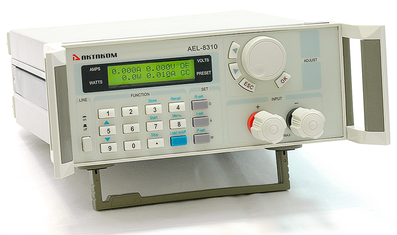
-
A whole new design with 250W for the base model At least they addressed the lack of CV and added a shitload of modes
I guess it isn't designed by Xiao Tony right? -
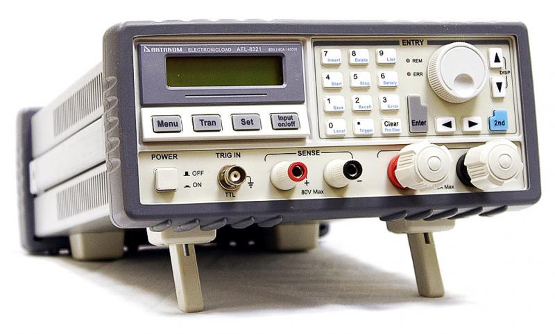
The AEL-8321 is likely the higher end 400W model, Array 3721a. I hope someone one day tears it down, because it appears to have different capabilities from the BK, Maynuo or Itech models 85xx series. Anyone can compare just searching tabao.com that the price is very competitive with local China prices, particularly once you add in S&H, so if they charge more it might be made quite differently, better I hope.
Spec wise the AEL-8310 appears as the Array 3710a entirely.
A whole new design with 250W for the base model
At least they addressed the lack of CV and added a shitload of modes I guess it isn't designed by Xiao Tony right? -
... and the numeric keypad is laid out properly - Hurrah!
-
Hey guys,
I am new to this forum and am so happy I have found it. I have read every post you guys have written about electronic loads.
I am currently working with an Array 3711A and am not very happy with it. It works great for discharging but I am having serious problems with the remote control. I would like to do some basic control using MATLAB and the constant resistance function in this device but I have serious doubts about it's functionality for this purpose. I have noticed that when the device is programmed at lower resistances (<250 Ohm), it produces erroneous current measurements. Could this be to do with the input terminals? The device was previously used.
Can anyone recommend a load which may be better for electronic control? I am considering a BK Precision but am not sure yet.
Thanks,
Katalyst -
Great to find another interested reader. The native software is buggy but crmaris has made a customized programmed suite to remote control 4x 3711a and 3x 3710. This suggests to me the drivers are OK. I collect data using the battery charger software but if I try to control the unit by sending commands using the native Array software, its erratic. It works accurately when operated via the keypad for all the supported modes, C, R, and W. I'll recheck your ohms issue.
http://www.techpowerup.com/articles/overclocking/psu/161
A previously used eload can be problematic as it can be damaged if misused, or abused.Hey guys,
I am new to this forum and am so happy I have found it. I have read every post you guys have written about electronic loads.
I am currently working with an Array 3711A and am not very happy with it. It works great for discharging but I am having serious problems with the remote control. I would like to do some basic control using MATLAB and the constant resistance function in this device but I have serious doubts about it's functionality for this purpose. I have noticed that when the device is programmed at lower resistances (<250 Ohm), it produces erroneous current measurements. Could this be to do with the input terminals? The device was previously used.
Can anyone recommend a load which may be better for electronic control? I am considering a BK Precision but am not sure yet.
Thanks,
Katalyst -
Anyone know of any guides/manuals for the actual setup for using using a bipolar operational power supply (4 quadrant) as an electronic load. Specificaly how to accomplish CC CV CR CW modes of operation. I realize some of these modes may require additional circuitry to control the source/sink unit. I just got a new unused TDK/Lambda/Electronics measurements inc. BOSS20-10-1-D-PM Bipolar Operational Source/Sink Power Supply ±0 - 20V, 0 - 10A off Ebay.
I am not looking to be spoon fed, just get me pointed in the right direction. -
Hi robrenz,
It may be described in manuals for the 4-quadrant supply you have. As example, Agilent N6700 Modular Power System SMU user manuals describe the adjustment to provide CV and CC like modes. Called downprogramming, the main drawback to using such supplies is that if the source stopped sinking current the PSu could then start supplying it to the source [ it could be programmed to not do so, but it depends on your unit], and could be a problem. Note capability differs in other members of the SMU family, mostly are capable of CC but not CV. I'm not sure about CP. The N678xA manual describes using it as a CV or CC sink.Anyone know of any guides/manuals for the actual setup for using using a bipolar operational power supply (4 quadrant) as an electronic load. Specificaly how to accomplish CC CV CR CW modes of operation. I realize some of these modes may require additional circuitry to control the source/sink unit. I just got a new unused TDK/Lambda/Electronics measurements inc. BOSS20-10-1-D-PM Bipolar Operational Source/Sink Power Supply ±0 - 20V, 0 - 10A off Ebay.
I am not looking to be spoon fed, just get me pointed in the right direction. -
I just saw this;
http://www.ebay.com.au/itm/150792412128
and thought immediately "well, someone must have held a grudge against those loads"