I was offered a Racal 9921 recently for about the same as a round of drinks. Despite the promise that it was completely broken that sounded like a good deal. While frequency counters are probably not that much use for general electronics they are still useful pieces of equipment - especially for radio amateurs so I thought some photos might be of interest.
First a word about the
Racal 991x series counters. Examples crop up on ebay fairly often along with the related 990x counter timers, the most common probably being the 9916 which covers the range 10Hz to 520MHz with two inputs. In the 9916 the higher frequency range is pre-scaled by a factor of 10 whereas it's a direct readout in the 9917, 9918 and 9921. There's a 1.1GHz model but I don't recall ever seeing one on ebay.
The 9921 is pretty much the flagship model covering 10Hz to 3GHz in three ranges - a high impedance 10Hz to 100MHz channel which has a sensitivity of 10mV but is protected up to 250V RMS (never been brave enough to prove that!), a 50ohm 40Mhz to 560Mhz input which also has a sensitivity of 10mV with a maximum of 5V RMS (protected up to 35V) and a 50ohm 300MHz-3GHz channel pre-scaled by 200 and with a sensitivity of 50mV.
They're pretty old now having gone out of production in the early 80s replaced by the 19xx series counters. The one I have appears to have been built around October 1979 so it's now 34 years old. If you're looking at one on ebay it's worth knowing that although they're mostly built using LS TTL there are a couple of parts that are now
very hard to find so a non-functioning one might be difficult or impossible to fix.
The design is a straightforward "count input pulses for a specified gate period" one - no reciprocal counting or timing error correction. The counter-timers have a "period" mode which does a reciprocal count but you have to remember to convert from time to frequency yourself. On the frequency meters gate times are typically 10ms to 10s in four ranges, the counter-timers have a wider range of gate times. To counteract the loss of accuracy at low frequencies some models have an optional LF multiplier which multiplies an input signal in the range 10Hz to 5kHz by 100.
Most have ovened oscillators - the basic unit is the 04A which has a 3 parts in 10
9 per day stability. The better ones are the 04B or 04E ovens. Avoid anything with the 04C oscillator which is an un-ovened basic crystal oscillator designed for units intended to be used with an external standard. Bear in mind that the external standard input on these is 1MHz, not 10MHz which is pretty much standard now.
The 9921 is not only the flagship but also the largest of these counters housed in a sturdy aluminium frame measuring in at some 35.5cm wide and 30 cm deep.
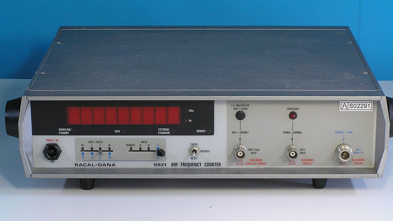
That's not mine BTW but a stock picture I pulled off the 'net (lightly edited) to show what one in good condition should look like.
It was a bit poorly when it arrived - no input worked. In fact check mode didn't display 1.00MHz on the A or C channels but did light up all 8's on the B input, except that the least significant digit wasn't lighting at all and the B channel overload indicator was lit whenever the channel was selected, even with no input.
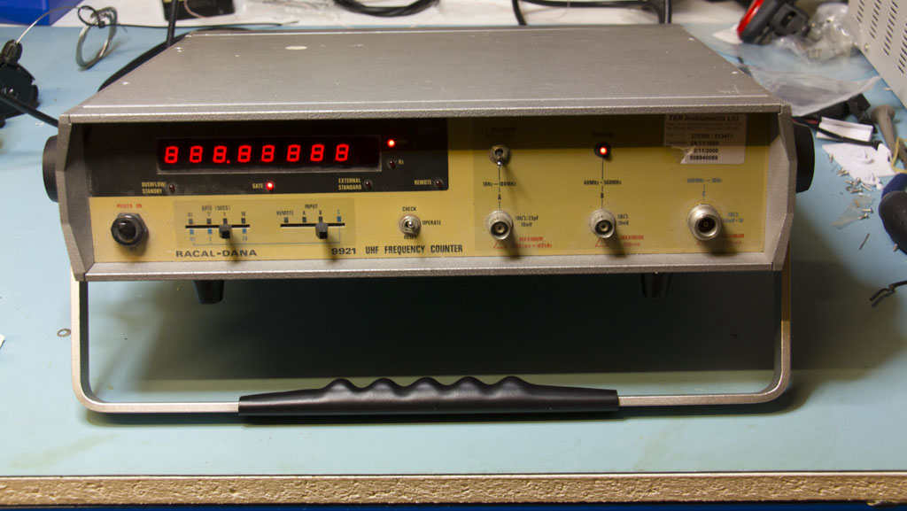
Counter in unhappy mode.
It also started to smell hot within half a minute on the bench, which turned out to be the mains transformer so there was obviously something amiss.
The original owner had already done quite a lot of work replacing the bulk of the electrolytics and several tantalums without any luck but that did eliminate some potential problems.
The inputs of these counters rely on various
Plessey high speed ECL counters. The 9921 uses an SP8635B which is a 600MHz divide-by-10 counter with BCD outputs. If these die then forget it although there is an ebay vendor with a few of the SP8630B used in the 9916.
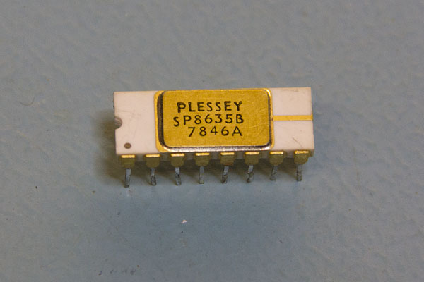
Purest unobtanium

Given the lack of the leftmost digit which is driven from the SP8635B I suspected a problem there and checking the rails revealed no -5.2V. As the regulator was not hot I assumed the problem was a shorted bridge so replaced the diodes (though it turned out I was out of 1N400x's and Maplin could only manage 3x1N4007 and one 1N4002!) and re-replaced the 2200uF cap - that got the -5.2V back, a happy transformer and the least significant digit but no joy on the check mode and no counting.
Further checking the SP8635B 600MHz revealed the problem was a dead chip - the 1MHz check signal was going in and there was a bit of activity on the BCD outputs but no 100KHz from the carry. Fortunately I did have a spare in a 9917 which counts erratically. I haven't yet found time to look at it to discover why so it was an ideal candidate for a donor. Transferred the IC to the 9921 and bingo, check mode now showing 1MHz (well, 1MHz plus one count which is often the case with the 99xx series) and channels A+C were working - at least as much as a brief test could tell.
Channel B was still out but that turned out to be the fact that I had cracked a small resistor next to the ECL chip - as that fed the signal into the "low level inhibit" circuit it basically behaved as though no signal was applied.
The 9917 didn't really survive the removal of the SP8635B - despite being careful the tracks seemed to be glued to the PCB with wallpaper paste and I lifted a couple of pads and tracks. So I now have a working 9921 and a dead 9917 (well, channel B is probably OK) - given the fact that the 9921 is the better counter that's much better than a dead 9921 and a not-working-enough-to-be-useful 9917.
On to the teardown pictures. Once opened you can see the main PCB - very similar on all of these counters. In this picture the A+B channel analogue input is bottom left, OCXO bottom right, PSU top right and the digital section in the centre centre through to the display drives and display board ribbon cable top left.
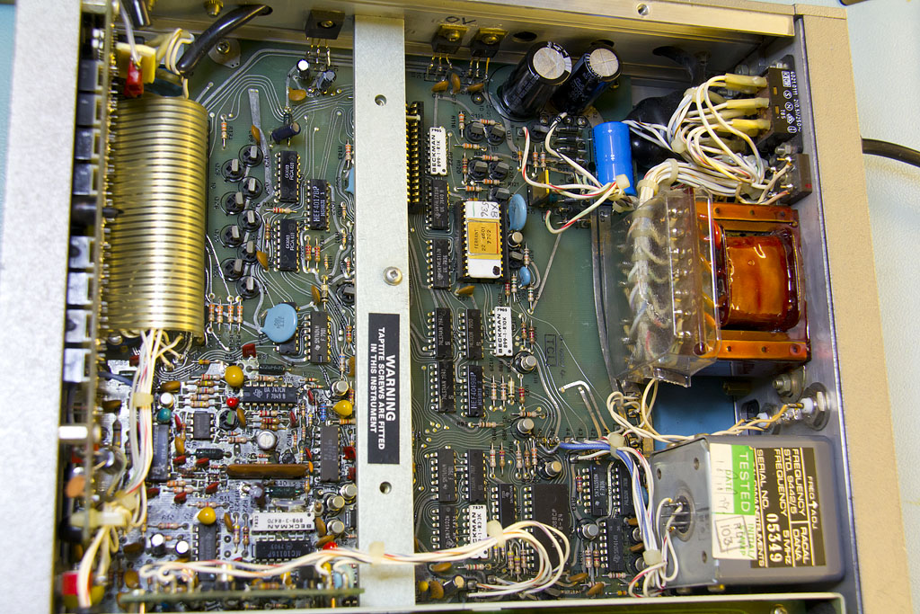
Here is a detailed shot of the PSU with new bridge and caps (which had already been replaced). The 24 pin Ferranti chip in ceramic carrier is another piece of unobtanium. This is the "CDI Chip" - basically the main logic of a counter-timer custom built for Racal. If this has died then you're out of luck unless you can get one from another 9900 series unit - they're all the same. Racal did make promises about free replacements for the lifetime of the counter so it's always possible that they still have some in a dusty corner somewhere but, sadly, the promise is only good for the original purchaser!
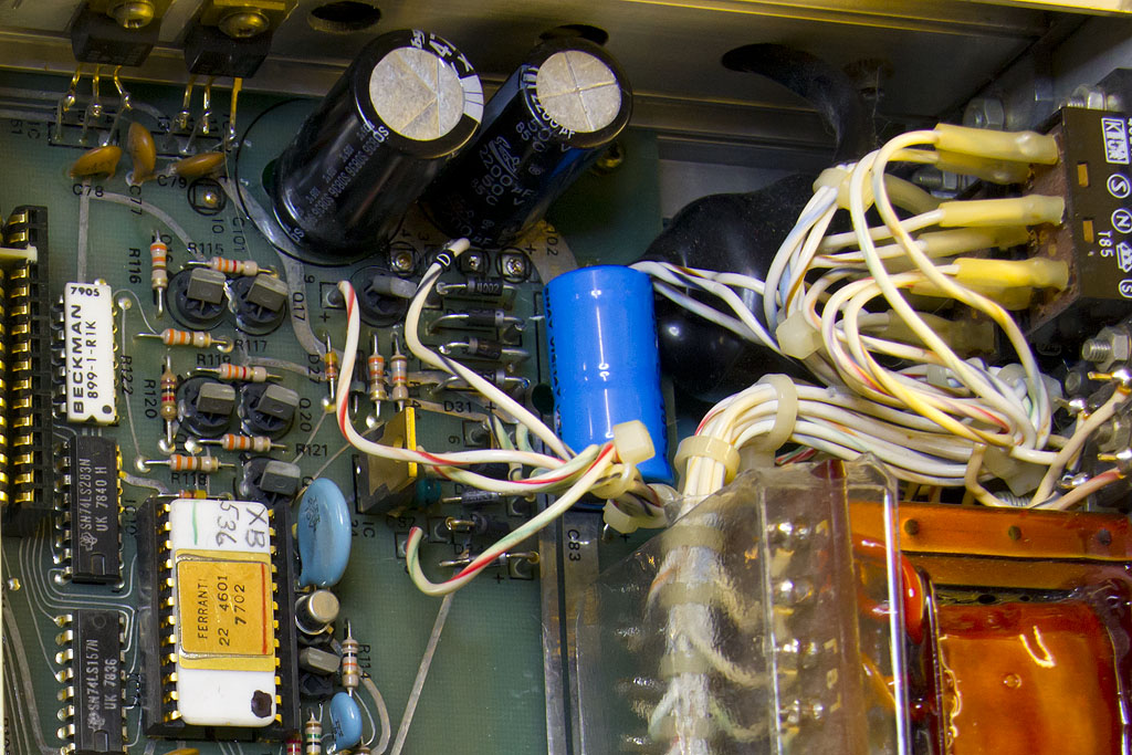
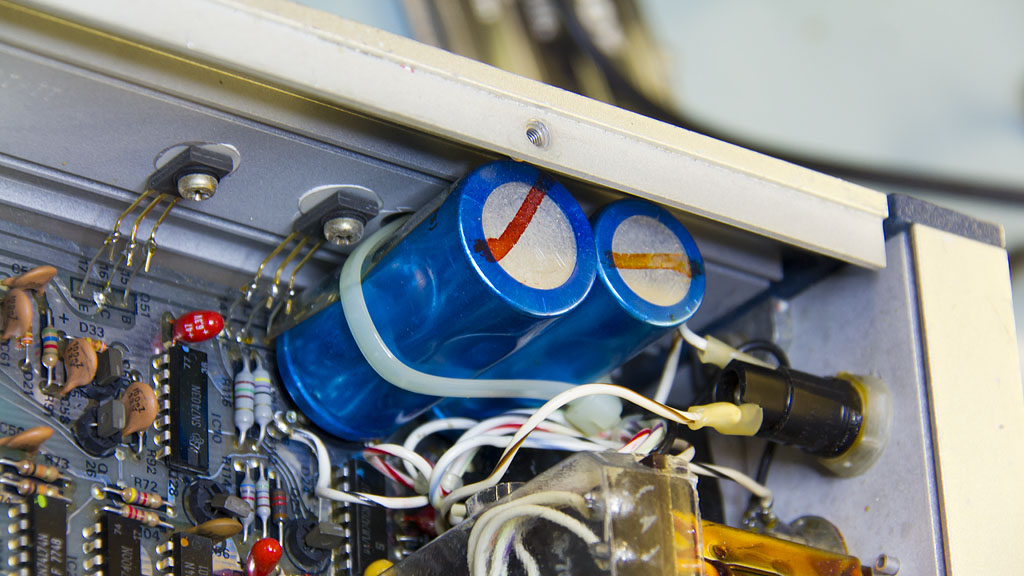
The original PSU caps are a Philips "snap in" version except, strangely, the terminals poke through rather large holes in the board and are then jumpered across to terminal posts. I'm not sure why Racal did it this way. You can also see the positively weird way that the voltage regulators are mounted.
The same area in the 9917 shows the original caps.
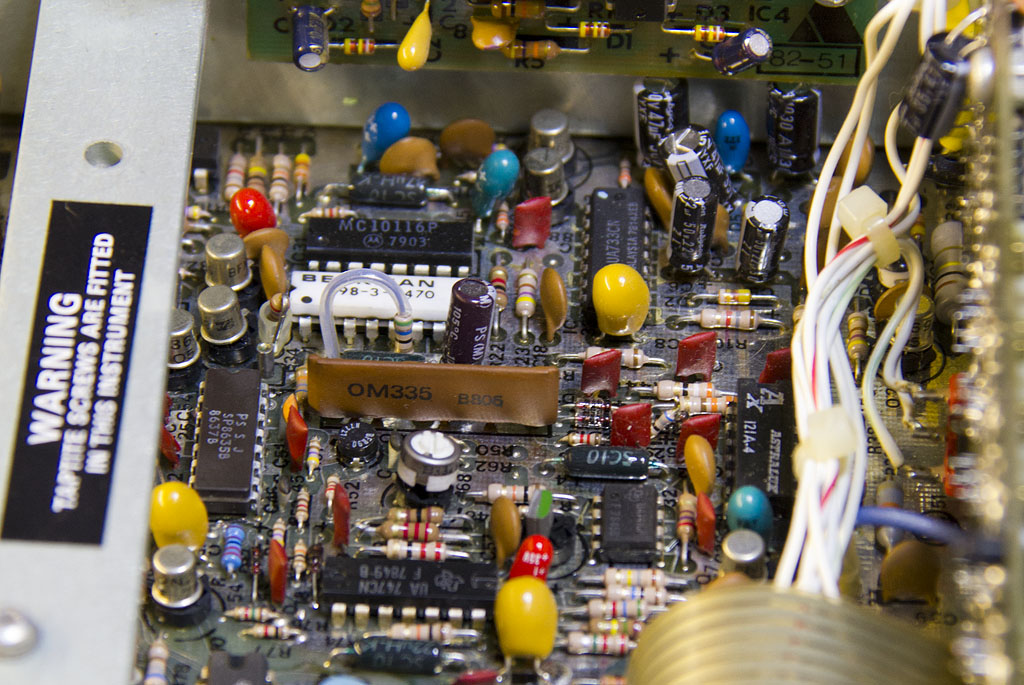
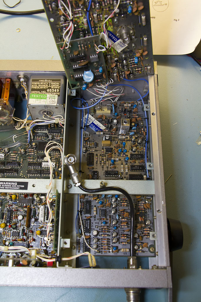
This shot shows the analogue section on the main board - the A and B input channels. The B channel in particular has a couple of troublesome components - the OM335 UHF amplifier hybrid and the PIN diodes used for the input attenuator and AGC. Actually the OM335 isn't
too bad - there are a few kicking around on ebay from time to time and there have been various projects to build replacements, especially as some of the Marconi signal generators use them. If the OM335 seems to have no gain it is worth checking that it's 24V supply is OK. On several of the 99xx counters this is generated from a small DC-DC converter and the tantalum smoothing capacitors have a habit of going short circuit.
The SP8636B can be seen just to the right of the warning about taptite screws - not sure why we need a warning about taptite screws, but there you go.
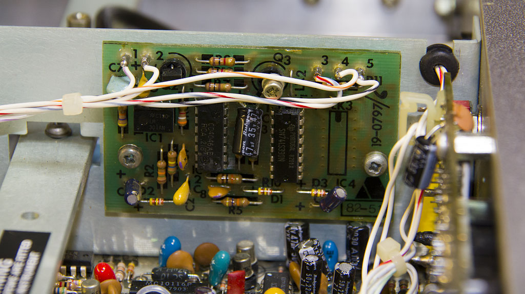
Just above is the LF multiplier board - basically a 100x frequency multiplier built around a CMOS 4046 PLL to generate an output 100x the input, again common to several of the counters in this range. I must have a more detailed look at this as the board doesn't tally withthe circuit diagram. It has a single 74LS390 dual decade counter rather than two 74LS90's
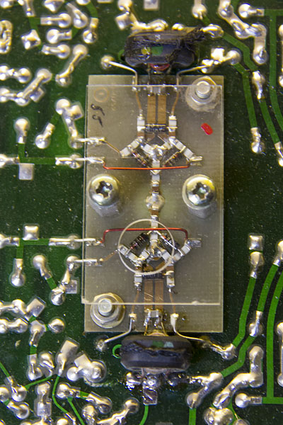
The next two photos show the 3GHz prescaler. I'm rather glad that this section appears intact because I didn't fancy delving in to fault find. It uses two sampling mixers together with two local VCOs running in the range 19-21MHz - one tracks the input frequency (such that one harmonic of the local oscillator corresponds exactly with the input frequency), one tracks at a frequency 399/400ths of the first such that when this is fed to the second sampling mixer a beat frequency is generated which is 1/400th of the input. This is then doubled to give an overall division of 200 and fed to the rest of the counter.
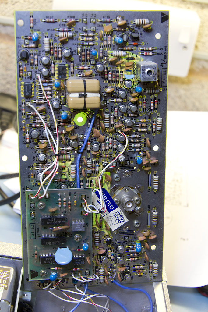
The two sampling mixers, note the interesting surface mount construction. This is really the only bit of the counter which actually operates at 3GHz - everything else uses the beat frequencies that this generates, although the local oscillator pulse chains do need sharp edges as we're relying on their harmonic content.
Success! The C channel showing the output from
my Marconi 2024. Of course that only goes up to 2.4GHz so I now need a sig gen that goes above 3GHz to fully test the counter. Clearly once I've got that I'll need a better counter to fully exercise the generator.....

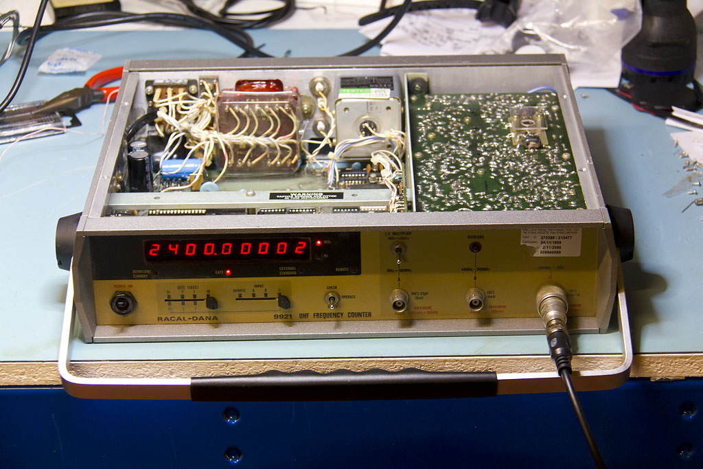
I just need to clean up the front panel and straighten the switches now. I'm not sure whether the yellowish colour of the front panel is original - all the others I'e seen have been grey - one thing I can say is that it hasn't changed colour in the last 14 years as it's the same under the calibration sticker which is from 1999.
Service manuals at
http://www.ko4bb.com/manuals/index.php?dir=Racal/Racal-Dana_9918_9921