I'm developing an open hardware microwave network analyzer as a hobby project, I thought I'd post it here to
increase my post count to qualify for the eevblog tequipment discount code share it with y'all.
This is first attempt at building test equipment, I welcome any feedback. I'm not expecting this to compete with $20,000 Keysight VNAs, I'll be happy with 60 dB or so of dynamic range up to 10 GHz with measurements within about .5 dB of reality. I'm still working on bringing up a prototype, currently only 1 port measurements from about 2 GHz to 5 GHz are mostly working. Over the next month or two I hope to have two port measurements between 2 GHz and 10 GHz.
This isn't the Henrik Forsten's network analyzer that you may have seen recently, he scooped me by a few months (
http://hforsten.com/cheap-homemade-30-mhz-6-ghz-vector-network-analyzer.html). If you are looking for something to build, his is the better choice at the moment.
The VNA is a bog standard 4 receiver design, all of the hard work is done by MMICs and off-the-shelf modules. Here is a picture of my prototype, it a bit of a mess at the moment:
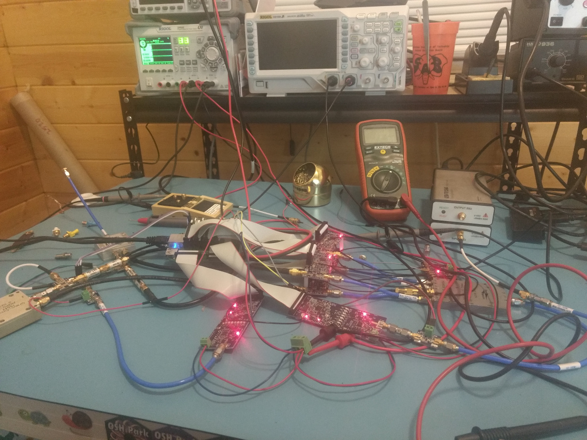
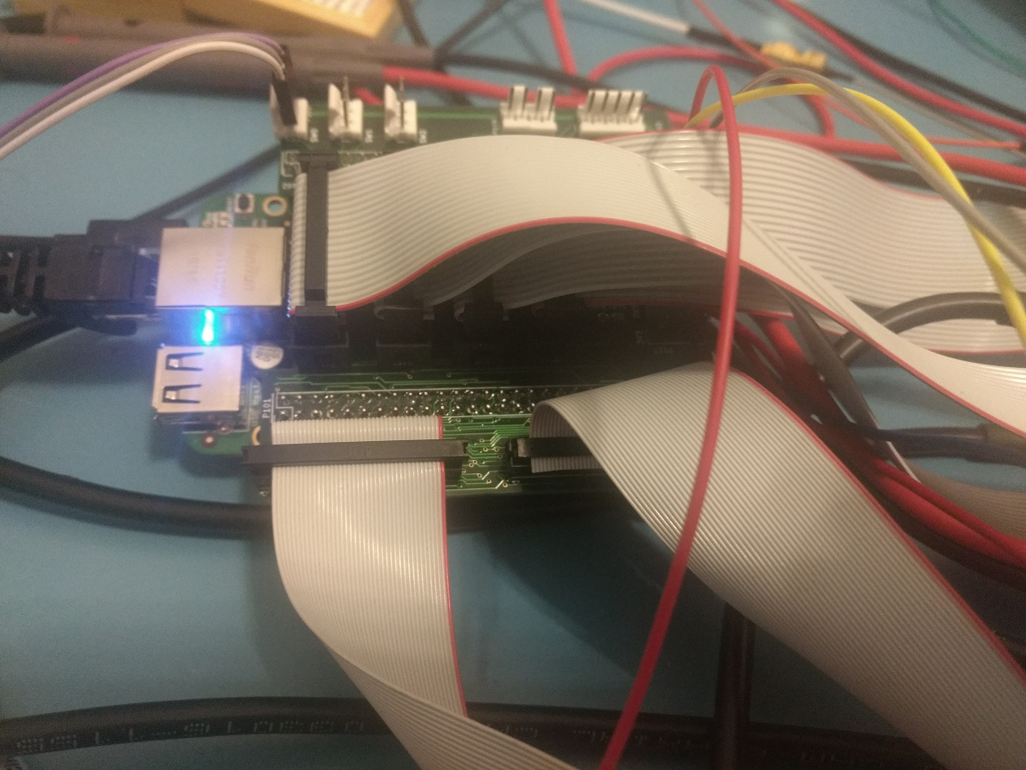
The VNA is controlled using a BeagleBone Green, with a PRU reading samples from four AD9864 IF digitiziers. An EMC nightmare of ribbon cables erupting off a custom
shieldcape ties together everything. I'm considering spinning a custom board around an Octavo OSD335x once everything else is working.
The VNA works by injecting a signal into the device under test and comparing the injected signal with the reflected signal. This design has a non-zero IF, so it needs an RF and LO.
These are generated by frequency synthesizer boards. I built them around TI LMX2592 20 MHz to 9.8 GHz synthesizers with some extra circuity for variable attenuation and filter banks. The BOM cost of these is about $300 each, I'm sitting on a unbuilt redesign which should cut that to about $150. These could be useful as a low cost standalone microwave signal generators. Earlier revisions had a power detector and amplification that I took out to reduce complexity.. I may add those back in at some point..
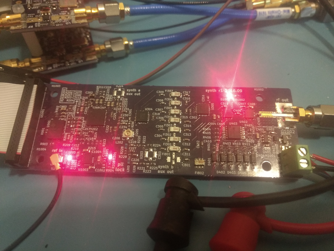
Mistakes on the filter footprints limit the usefulness of these above about 6 GHz. I'll fix it in the next revision.. until then, I'm using an external multiplier. For the LO, the LTC5548 mixer has a built in multiplier. For the RF path, I'm planning on switching in an AMMP-6120.
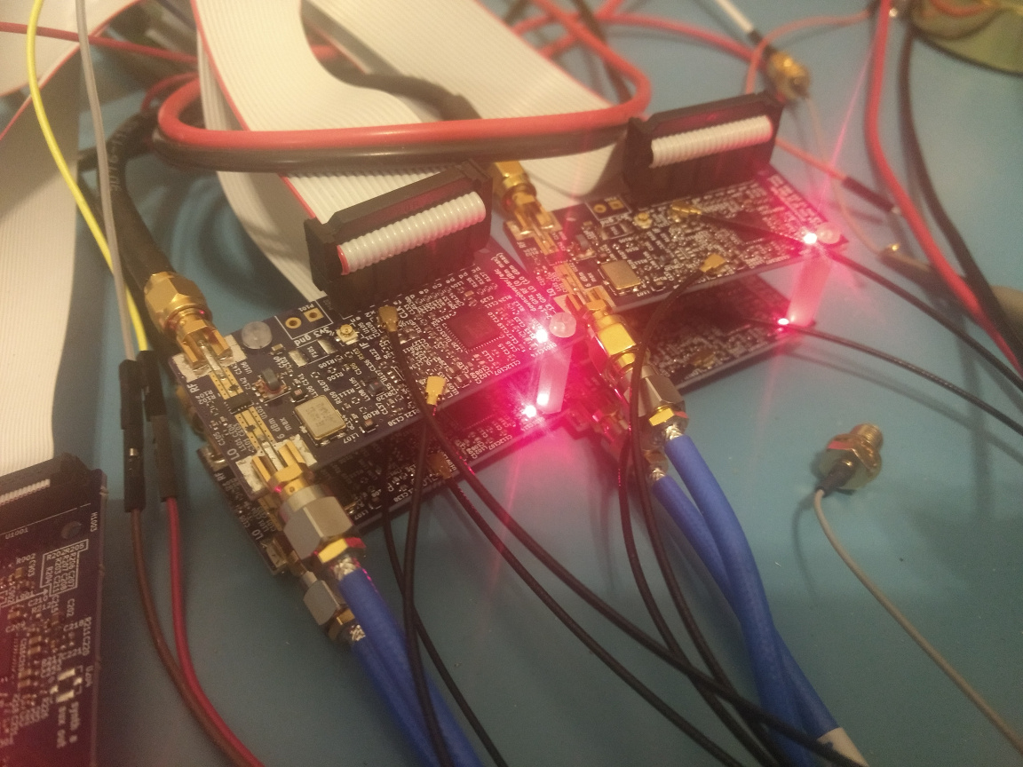
The receivers are built around the LTC5548 mixer and AD9864 ADC. I designed them to also be useful for a Greg-Charvat-style through the wall radar, there is a crystal filter in the IF path.
So far only one port measurements are tested and they are still a little wobbly. Here is an example plot of S11 of a 10 dB attenuator after short/load/open one port calibration (ideally, this would be a flat S11 of -20 dB):
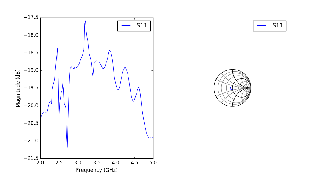
As y'all can see, it isn't working perfectly yet. I still have some work to do on the software, and some of the harmonic filtering for the synthesizers is bypassed due to fried pins until I order a fresh BeagleBone.
After I add in a multiplier and finish the software for two port measurements/calibration, this is expected to work from about 2 GHz to 10ish GHz. I plan to use this as a testbed for attempting more ambitious measurements such as triggered and pulsed s-parameters, cold source noise figure measurements, time domain analysis...
All the software and hardware is available on my github under an MIT license:
https://github.com/loxodes/vna. I'll post occasional updates here as I get more things working.


