Let me start by saying that, what follows, doesn't pretend to be "the definitive guide" or something like that, but just some notes about putting up a well performing "random" wire antenna covering the HF bands; the below is just some kind of "digest" coming out from informations I've collected from several sources (internet ones are reported) and from personal experience.
* Note about antenna wire selectionIn what follows I'm referring to stranded, insulated copper wire (for the antenna and counterpoise wires), but if you prefer using solid and/or bare wire, it will be ok too; things will change in case you'll use a different material (e.g. steel) since, due to the velocity factor of the chosen material, the suggested lengths may change and the resulting antenna may not work as expected, also notice that when you'll choose your wire, it will be a good idea avoiding too thin wire, since it may break more easily, a good pick would be a wire diameter around 2 or 2.5 mm (AWG #10 to #12) since it's thick enough but not too heavy, then, the choice is up to you
* Antenna wire lengthFor a full discussion about best wire lengths to use for a random wire antenna, see
http://www.hamuniverse.com/randomwireantennalengths.htmlin short, to be efficient on a given band, the wire must be longer than 1/4 lambda on that band and must NOT be a multiple of 1/2 on ANY band which we want to use the antenna on, so for ham bands here's a table summing up the best lengths up to 423ft, the "band" column shows the "lower" (longer wavelength) band on which a given length of wire will operate in an efficient way (longer than 1/4 lambda), when possible pick from the table the longest length which fits your available space
band mt wire meters wire feet
-------- ----------- -----------
20 8.84 29
40 10.82 35.5
40 12.50 41
40 17.68 58
80 21.64 71
80 25.60 84
80 32.61 107
80 36.27 119
160 45.11 148
160 61.87 203
160 105.77 347
160 124.05 407
160 128.93 423
-------- ----------- -----------
the antenna wire should, if possible, be laid out in a straight line, and even if the horizontal placement would be the best one, it may also be laid out in a sloping configuration; if this isn't possible, and/or if you want a longer wire to cover a lower band, you may lay it out in a "zig-zag" fashion, taking care that it never describes an angle of less than 100°; in this latter case the radiation pattern will be almost unpredictable and the SWR may be a bit higher, so if possible, try to keep is straight or at least try to keep most of the antenna straight
* Counterpoise/groundingThe "random" needs a counterpoise to work properly, such a counterpoise may just be a run of wire connected to the "ground" of the UnUn,
according to the ARRL informations, a good counterpoise for a random wire antenna should have a length of 1/4 lambda at the lowest operating frequency (which for the 160m band means 40m/131ft - but don't worry and read on), such a counterpoise may be just laid down on ground in a straight line and/or looped around trying to keep the loop as large as possible; alternatively it's possible to connect a run of wire from the counterpoise connection to the ground and, from there, run whatever number of radials of various lengths and in various directions, another alternative could be using some metallic wire net (the so called "chiken fence") laid down on ground and connected to the wire going to the UnUn ground binding post; if your feedpoint is high enough here's an idea for a simple, yet effective, counterpoise system
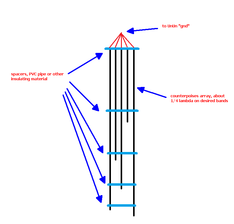
in the above sketch, the black vertical lines are the counterpoise wires which should possibly be cut around 1/4 wave at the various bands, the longer ones may then even lay on ground (use insulated wire), the red lines are the top junction going to the UnUn "gnd" post and the blue horizontal bars are spacers built usin some insulating material (small diameter PVC pipe will do)
* FeedingWhile a "random" may be fed directly to a tuner, to avoid the (very bad) "RF in the shack" you'd need to use a remote tuner, otherwise an easier yet effective way of feeding the "random" is using an UnUn (since it is an Unbalanced antenna), now if we build the antenna using one of the above lengths, its feedpoint impedance will be around 450 Ohm on the Ham bands, so to bring it back to 50 Ohm and feed it using a standard coax cable we will need a 9:1 UnUn, the informations to build such an UnUn can be found at this page
https://vk6ysf.com/unun_9-1.htm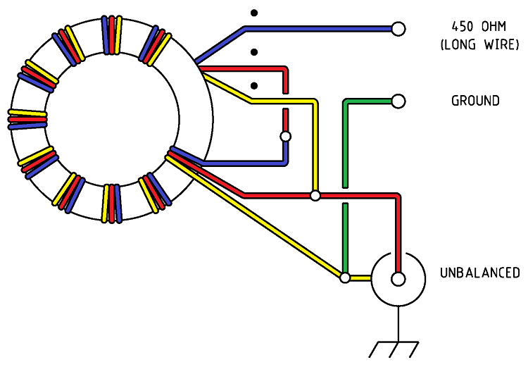
but, instead of using a "T" series toroid, which has linearity issues if used as in a wideband transformer (it's an high "Q" mix toroid), it's better to pick an "FT" series one, a good pick could be a #43 material, for example an FT240-43
http://toroids.info/FT240-43.phpusing an FT240-43 toroid your UnUn will be able to support at least 400W continuous operation, if you use less power you can go for a 140 which will allow around 150W, if you need more power, pick two 240 and stack them one over the other before winding the wire; in any case, put your UnUn inside a good water/weather proof enclosure, the enclosure will then host a hook/eyelet to hold the unit up, two binding posts for the antenna and the ground/counterpoise and a coax connector, here's an example showing a good way to put things together (note the image is NOT referred to the 9:1 UnUn seen above, I use it just to show an idea showing how to correctly host it inside a box and how to setup the various external connections)

just ensure to seal all the connector/post/hook holes to avoid problems with water/mist, if you want, you may use some tape to stick, to the inner side of the cover (not shown in the above image) a bag of dessiccant (e.g. "silica gel") which will help keeping the box content dry
* ChokingBeing an unbalanced antenna, even if we are using a counterpoise, the "random" will need a choke on the coax feedline to stop common mode currents from causing issues, the simplest way of building such a choke will be using a #31 material toroid to wind a "guanella" choke over the coax cable, the instructions to build such a choke can be found here
https://www.dj0ip.de/rf-cmc-chokes/different-kinds-of-chokes/d2-guanella-choke/
notice that it would be a good idea adding a second choke at the point where your coax feedline enter the shack to further help removing CMC, be careful to "hang" the choke(s) and not to lay them on ground; if you don't have toroids for the choke, a less efficient alternative could be winding about 10 turns of coax to form a 30cm (12in) coil, ensuring that the two ends of the coil come out to opposite directions and that the loops are properly wound, possibly use a former (e.g. a piece of PVC pipe or the like), the result could be something like these


and, as you can see, such chokes would be quite bigger than the "guanella" type one (and the bandwidth at which they'll be efficient will be narrower), but if you'll decide to go for such a design, check this site for additional informations
http://www.hamuniverse.com/balun.html* Assembling the antennaStart by selecting the desired length (usually the longest one which fits your available space) from the table we've already seen, then measure the wire to obtain a length sligtly (say 20cm / 8in) longer, measure the wire again leaving half of the excess at both ends and mark the points with some tape, then just to stay on the safe side, measure the length between the tape markers again
Insert one piece of shrink tubing at one end of the wire (this will be our remote end), fold the excess wire over the antenna near the tape marker, lock it with two spaced nylon cable tiers, now fold the end of the excess wire back again toward the end and place two more nylon tiers at the spacing points of the first two and use them to lock the three wires (antenna, first fold and second one) together, add a third tier passing through the eyelet formed by this last folding (the one which is over the antenna, not at end); cut the excess from the nylon tiers, slide the shrink tubing over the tiers/folded wire and warm it as needed, cover the tubing with UV resistant duct tape
Repeat the above for the other end of the wire (feedpoint) but this time slide THREE shrink tubing over the wire, use one for the "eyelet" as we did above and leave the other two alone along the wire (do not shrink them - we'll use them later on)
Now you should have a wire with two eyelets at its ends, it's time to add your feedpoint; gently remove a short run of insulation from the end of the wire (near the point where you placed the marking tape), to expose the copper and slide one of the two shrink tubings toward the end (the eyelet) of the antenna wire so that the two tubings will now sit at both ends of the exposed portion, pick another piece of wire of appropriate length (say 20cm / 8in at MAX), remove the insulator for a bit from one end, wrap that end of the wire around the exposed point of the antenna wire and solder it, try avoiding to melt the surrounding insulator; done so slide the two shrink tubings over the junction point and shrink them, slide another tubing over the soldered wire up to the junction point and shrink it too, now wrap the whole area with teflon tape and then wrap the teflon with amalgamating tape, once done cover the amalgamating tape with UV resistant duct tape and the antenna wire will be almost complete; remove the insulator from the end of the "feed wire" (the one we soldered), slide another shring tubing over the wire and add a fork spade "U" or ring wire crimpable connector, solder and crimp the connector, slide the tubing over it and shrink the tubing, cover the tubing with teflon tape, amalgamating tape and UV resistant duct tape, that will be the connection between the "random" and our UnUn
Prepare the counterpoise, as I wrote above, use whatever method you prefer (or fits your available space), just ensure to add a fork spade or ring connector to the wire end of the counterpoise which will go to the UnUn "ground" binding post to ensure you'll have a good connection to it
* Installing the antennaPlace two steel pulleys to the points where the antenna ends will be placed, the pulleys may be directly tied to the supports or you may use some rope to tie it, if possible try to keep the feedpoint end at at least 9mt (29ft) and the far end at at least 3m (9ft), if not, do your best to keep the antenna as high and free from nearby buildings/wires/poles as possible
Cut two pieces of rope, the length of each will be the double of the distance between the pulley and ground (or the terrace floor or in any case, the point where you can comfortably service that end of the antenna)
Tie each piece of rope to the corresponding "eyelet" present at the end of the antenna wire, to tie them, I suggest using a
bowline knot and then locking the knot end with a pair of nylon tiers, pass the other end of the ropes inside the pulleys and down to ground and tie a simple knot to keep them from sliding (such a twin pulleys setup will allow you to easily lower the antenna to inspect or service it)
Time to raise the antenna; start from the feedpoint, hang the UnUn to the rope near the antenna end, to do that, wrap some tape over the rope and use some nylon tiers to hang the UnUn, don't pull the tiers, leave them forming some loop so that the rope won't be shrinked, then use two or four additional tiers to lock the "loop" at the desired position, such a setup wont put strain on the rope reducing its resistance; done the above, connect the coax (which should already have the choke) to the UnUn and pull the rope until the distance from the antenna and the pulley will be around (or possibly more than) 1mt (3ft), tie the rope with a simple knot, just to avoid it slides out and move to the other end of the antenna, raise it as needed and again tie with a simple knot check both ends and adjust spacing and tension as desired by adjusting the rope at both ends
Now, pick a pair of strong, empty plastic bottles, the ones used for chlorine or home detergents should fit, just ensure the bottles have a handle, a bottle like this (just an example) will fit well
https://hyclor.com.au/wp-content/uploads/LiquidChlorine.5L.jpguntie the rope and pass it through the handle of one of the bottles, pull the rope to put the antenna in tension and tie the rope to the handle with a good knot (a
hangman knot will do) ensuring that the bottle is sitting on ground when the antenna is in tension; now the "funny" part, pick up the (empty) tied bottle and pick a recipient (bottle...) filled with a mix of water and chlorine (the latter will be useful to avoid growth or organisms or algae), start filling the empty bottle (the one tied to the rope) a bit at a time until the bottle, due to weight, will sit on ground and the antenna wire will be in tension again, cap the bottle, seal it and repeat the operation for the rope at the other end, such a trick will keep the antenna in position BUT, if there's some load from wind/ice... it will also allow the antenna to lower (and raise back when the load disappears) so that the wire won't be subject to excess strain and break
* Testing and adjustingnow it's time to test the antenna, connect the coax to your TRX, set it to lowest TX power and test the SWR on the various bands, if things are ok, you should see an SWR at around 1.5 or even lower; notice that the random isn't a RESONANT antenna, so the only thing you can do lower the SWR (assuming you'll need to) is improving the counterpoise system, by making the counterpoise longer/better, that is adding radials and so on; but in general if you have a good counterpoise (as discussed above) your SWR will be quite low on all the Ham bands which the antenna can cover, the only bands which may, in some cases, need the use of a tuner are some of the WARC ones, but even then, the SWR would be low enough to be easily dealt with by a regular ATU
Once your SWR test and possibly some listening test will be complete, you may go on and check how the signal from your new "random wire" antenna is received at various spots, to do so, you may just use one of the (many) available public Web SDR receivers, here's a list containing some of them
http://websdr.org/ (also see them on a map at bottom of page), start by picking a receiver near to your spot, find a free spot on the desired band, and try transmitting, that will tell you if and how your signal is received at that spot and could be a first, coarse test, of your antenna performance
That's all, hope the instructions are clear and correct (if not... just tell me so, I'll edit the post); I just hope that the above could be of help to any new Ham willing to put up his first antenna !


