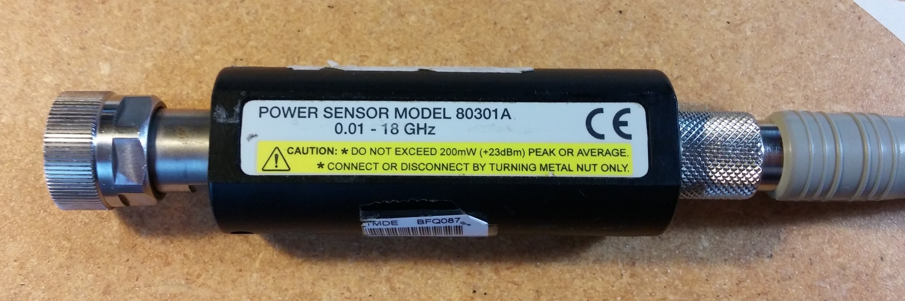
Bought a cheap power sensor on a gamble in untested condition, the gamble didn't work. Naturally, I tried every noninvasive option to see if I could get a response, then I cracked it open. Amazed at how little was inside, I probed around the sensor with a known-good input and got no response... so I took the teardown a step further and got all the way down to disassembling the detector. Enjoy the pics:
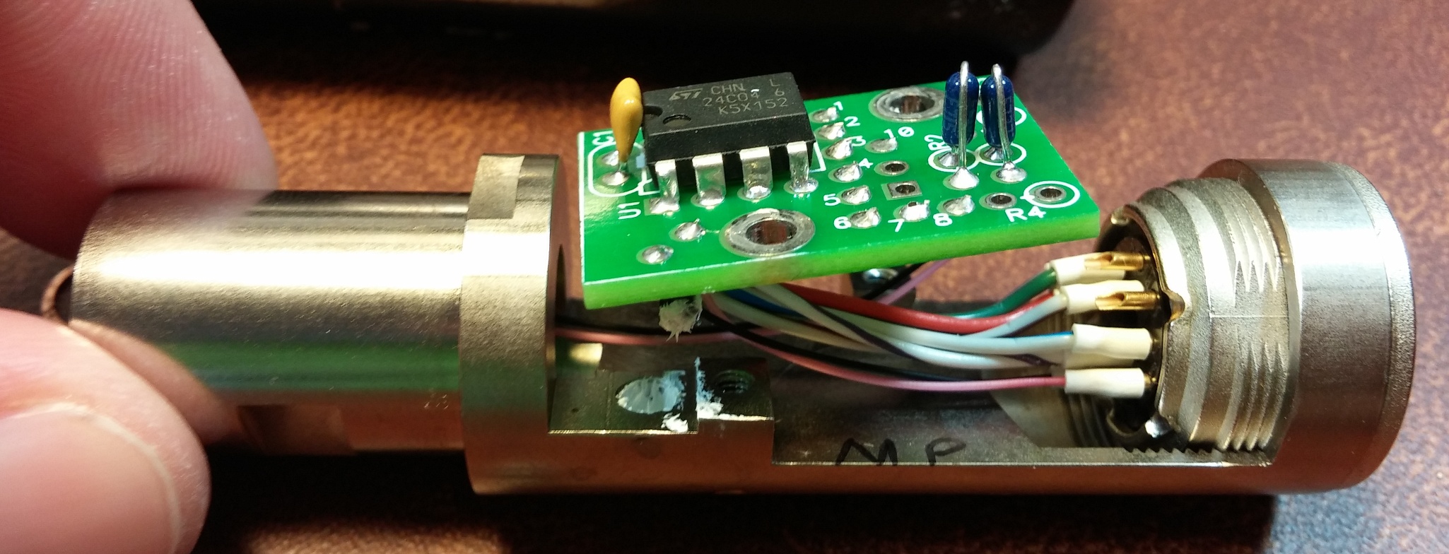
The PCB has almost nothing on it. A cheap eeprom, two resistors, and a bypass cap. On the underside there's a thermistor with some heatsink compound for temperature compensation. Nicely machined housing though, next to no chance of a failure due to a lose wire because everything is sturdily held down.
But can we go deeper.

Yes, we can. The detector is nestled in a heavily shielded, well machined, block of a shield. Suprisingly, it's not potted, but instead uses a split ring to hold on a cylindrical metal shield around it. Forgive the lack of a macro lens, but here's where the magic, and presumably the cost, is all happening:
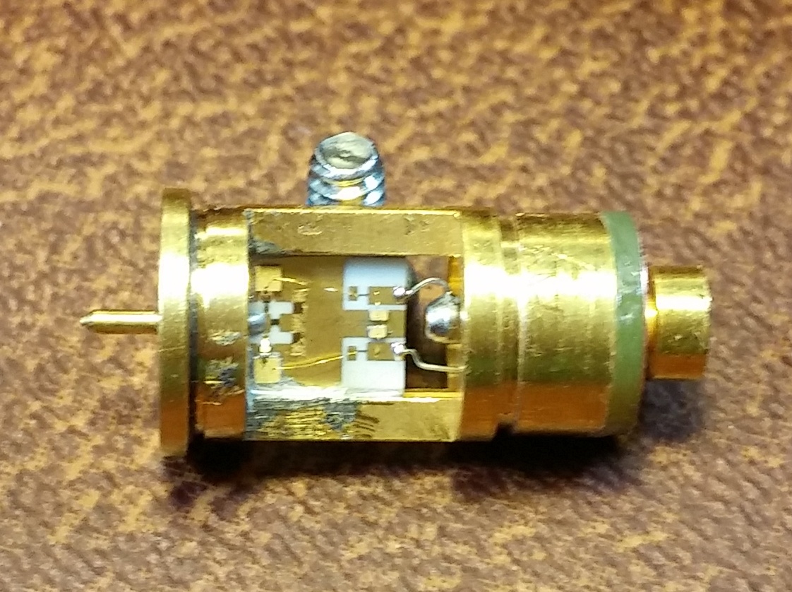
Despite the blurriness, you can sort of see the top bond wire looks different, and I think this is the failure with the whole unit, as there was absolutely no output and it's the only visible damage (though it took several looks through a jeweler's loupe to verify that it was actually broken).
I don't have any of the equipment or expertise to replace the bond wire, but I'm thinking of trying a hack with a strand from thin stranded wire that's pretinned, maybe with a tiny bit of solder paste on the pads trying to be bonded, and then rely on conducted heat from heating the top of the wire to make it join. There's no chance such a hack would be in calibration or would make a useful power sensor in the end, but it would be cool to get some output.


