Author Topic: DIY thermal RF power sensor?  (Read 6354 times)

0 Members and 1 Guest are viewing this topic.

Offline rf-filTopic starter

  • Regular Contributor
  • *
  • Posts: 54
  • Country: au
Re: DIY thermal RF power sensor?
« Reply #25 on: July 30, 2023, 03:49:07 am »
@switchabl

Over the past 5 years or so I have accumulated a suite of lab gear with a 1990s list price of in excess of $600k for 1-2 cents on the dollar.  This poses a significant cal issue as I cannot afford to send that stuff out for cal.


That's me as well. And now I'm in need to prove a radio RF power output complies to a local standard, without relying on my employer's gear.

I've run a very crude test just now. I strapped a thermocouple to a 20dB 50ohm attenuator and held it in front of a 12V fan with an alligator clip "third hand" fixture. Then I fed DC current into one end of the attenuator:
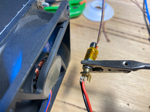


The results are surprisingly good:


The time constant was quite long. It took a minute or two to settle.  When I do linear regression on this, I get only 0.03dB of error.  The power range of a few watts might not work for everyone, but I'd be OK with this for my use case. One thing that works is that this uses a nearly perfect RF load. This attenuator is specified out to a few GHz. Using a small 50 ohm termination might work better.
Anyway, good discussion and input from everyone so far. I'll setup a pair of these sensors next, and see if I can keep the heat flow identical, so that the setup can then do real time DC substitution / comparison.

« Last Edit: August 21, 2023, 10:56:29 pm by rf-fil »
 

Offline dietert1

  • Super Contributor
  • ***
  • Posts: 2407
  • Country: br
    • CADT Homepage
Re: DIY thermal RF power sensor?
« Reply #26 on: July 30, 2023, 06:33:18 am »
Yes, this realizes the DC to RF transfer. It's fun and there is something to learn.
Don't you want to reduce the thermal mass of your sensor in order to get a one second or so time constant? Other people have used multiple SMD resistors to make a GHz terminator at the end of a coax cable, like 3x 150R. Or get a G150N50 at ebay (good up to 3 GHz). As soon as you have the time constant down you eventually find that a small oven with some thermal mass is more suitable than a fan. And running the sensor in compensation mode, i mean at constant temperature also helps with speed.

Regards, Dieter
« Last Edit: July 30, 2023, 06:34:53 am by dietert1 »
 

Offline rhb

  • Super Contributor
  • ***
  • Posts: 3501
  • Country: us
Re: DIY thermal RF power sensor?
« Reply #27 on: July 30, 2023, 01:05:23 pm »
For a precision reference a long time constant improves the accuracy.  The heat equation is an infinite sum of exponentials.  A long temperature vs time history will greatly improve the resolution of the coefficients, especially the constant in the exponent.

I am both surprised and encouraged by getting such results from such a crude device.

I was trying to reply last night but my ISP has borked their DNS & router tables in a manner that I couldn't even refresh my yahoo mail website Inbox.

I am queuing up some quality time with Carslaw and Jaeger's classic, "The Conduction of Heat in Solids".  Flipping through the pages I found analytic expressions for the temperature of a cylinder in an infinite medium.  I've not studied it yet.  What I saw was graphs of the first approximation.  The deviation from linearity is heat loss to the surrounding medium. 

Thanks for sharing your work.  I have a good (Clausing 4902) metal lathe, so making a bespoke thermal mass is not a problem.  Once we work out the details I'll be very pleased to make one and put it in the post to you.

The high specific heat of aluminum makes a long time constant especially easy to achieve.

I am insanely busy with ongoing projects which are higher priority, but I'm sure I can squeeze in a few evenings studying the mathematics this week. 

If you are impatient and want a hollow cylinder quickly, chucking  a 13 mm piece of aluminum in a drill press chuck and feeding it down on a drill bit so that the aluminum is rotating and the drill is stationary will quite precisely align the hole with the outside.

Have Fun!
Reg
 

Offline rhb

  • Super Contributor
  • ***
  • Posts: 3501
  • Country: us
Re: DIY thermal RF power sensor?
« Reply #28 on: July 30, 2023, 03:43:12 pm »
Would you please repeat the experiment with a couple of inches of loose cotton or polyester batting wrapped around the sensor?

If there is no heat loss, the graph should be perfectly linear.  This would give an idea of the magnitude of the effect of insulation on the linearity and how much insulation is needed.

Very nice work.  Thanks for sharing it.

Have Fun!
Reg
 

Offline rf-filTopic starter

  • Regular Contributor
  • *
  • Posts: 54
  • Country: au
Re: DIY thermal RF power sensor?
« Reply #29 on: August 21, 2023, 10:43:08 pm »
Next set of experiments - I've spent a bit of time figuring out the best RF load for this. I wanted something with smaller thermal mass and as broadband as reasonably achievable. Luckily, I have access to a good VNA at work.

First, I tried an SMT RF load, DigiKey part # 4244-A100N50X4A-ND. The load had a decent match up to 3.5GHz, even though it was just soldered directly onto RG405 semi-rigid cable. Not bad. But after that, I also found that, as per suggestions above (thanks!), just simply soldering an 0603 51-ohm resistor onto a diagonally cut RG405 semi-rigid cable works even better. The return loss plot shows that this will work up to 8GHz, depending on desired accuracy:


Translated into mismatch loss, this gives about 0.1dB accuracy up to about 3.5GHz.

I've now got some tiny RTD temperature sensors and associated interface boards. The plan is to glue the RTD sensor onto the RF load and go from there..

« Last Edit: August 22, 2023, 12:06:11 am by rf-fil »
 

Offline rhb

  • Super Contributor
  • ***
  • Posts: 3501
  • Country: us
Re: DIY thermal RF power sensor?
« Reply #30 on: August 26, 2023, 12:56:40 pm »
Those ripples in frequency are reflections between impedance mismatches at the ends of the cable as you are probably aware.  The magnitude of the mismatches will vary by part, but the timing won't as that's controlled by the physical geometry.

This implies the possibility of correcting them in software and controlling their spacing.  The longer the cable the closer the spacing of the ripples.  By my calculation your cable is about 10 cm.  Is this correct? If it is, I'd suggest trying the same but using a shorter cable or a bare SMA connector.

I am currently working on repairing a Wiltron 560-7A50 sensor which uses a diode and thermistor and is supposed to be good from 10 MHz to 20 GHz.  The capsule fell apart and the two wire bonded parts are visible.  It will require a shrink fit to reassemble which has me somewhere between scared and terrified.  I've attached photos of the sensor just in case it sparks some random inspiration for this project.

The sensor head had gotten wet which resulted in corrosion at the steel aluminum threads contact between the APC-7 and the aluminum PCB housing.  A suggestion by a member of the Anritsu-Wiltron list to use a dilute acid solution completely removed all the corrosion (50-50 vinegar & distilled water in my case) after a short time in the ultrasonic bath, but when I pulled the brass capsule from the APC-7 it fell apart onto my bench top.

If you don't have access to femptosecond TDR I'd like to examine the device from this post on my Tek 11801/SD-24 sampling scope when you are finished with your testing of it.  I'll cover mailing cost both ways wherever you are.

Have Fun!
Reg


Share me

Digg  Facebook  SlashDot  Delicious  Technorati  Twitter  Google  Yahoo
Smf