IntroductionDue to several antenna discussions on the forum I thought I should share my own trials and failures of venturing into the RF world in some effort to offer a little help to others venturing into this magical world of RF. So with this project log I offer some history for this project and some very simple guidance so that others might also achieve a satisfactory result.
I urge others to also share their experiences in following posts so to serve as a learning resource for readers attempting antenna construction.
A ten year antenna build for RF remote controlHistoryIt all stemmed from a need to control a water pump remotely and using a 4ch wireless system from:
https://www.rfremotech.com/DIY2BComponents.htmlTheir receiver module and transmitter would work past their stated 200m range but I needed ~500m and rather than get a higher powered transmitter that might exceed local EIRP regs for telemetry it was time to install some sort of receiving antenna in order to improve signal gain to the receiver.
Transmitter 315 MHz

A decade ago with no RF experience and limited knowledge some research was undertaken and after some study a omni-directional design was decided upon as there was a requirement to receive signals from ~120 degree directions so a whip/monopole was selected and built from materials on hand. Out of ignorance no ground plane radials were added resulting in RF performance that was next to useless and certainly no better than the short pigtail of wire the receiver was supplied with.
Bad antenna

Log Mag screenshot of old antenna with SSA3032X and Return loss Bridge indicates old antenna could be functional but not at the the intended 315 MHz where marker #1 is.

By trial and error it was found that a short length of stainless wire inserted into the control cabinet BNC gave good enough performance to the required distance but only if you had the keyfob transmitter antenna fully extended and held the tip of it between fingers. And so we worked with this for at least 10 years. Meanwhile the bad antenna remained installed pointing at the heavens as a reminder of my abysmal initial attempts at antenna construction.
Just this bit of wire worked !
 New Project
A decade later and with release of new equipment from Siglent, my SVA1015X arrived and it didn’t take long to find a proper project to test its capabilities as a spectrum analyzer and vector network analyzer.
Ten years older, a little wiser and now knowing that radials would have made the original antenna operative it was time to look at it in greater detail but sadly the nylon bushing the whip was installed into had suffered from a decade in the elements and it proved to be so well stuck into the galvanized pole that it broke with attempts to remove it. So now with no nylon rod on hand to machine a replacement it was time to start again.
Forum member GOHZU suggested I look at J-Pole antennas and at a glance they seemed simple enough excepting for a way to mount them but after a couple of days pondering the obvious emerged, in a capped PVC tube supported on the apparently mandatory feedline ferrite beads.
Good guidance of J-Pole design is here and embedded links provide more resources.
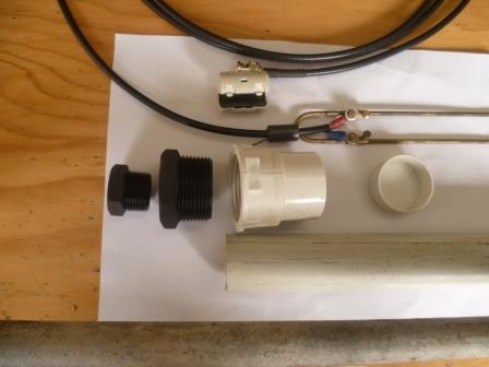
https://m0ukd.com/calculators/slim-jim-and-j-pole-calculator/Looking at the various materials on hand I had the choice of 1/8” brazing rod or 1/4” copper rod that is used for droppers from 11KV into powerco distribution transformers however the 1/8” brass rod was selected as rigid enough and easier to provide for the adjustable feed points necessary for desirably low SWR results. For the feed points I came up with a simple plan using the innards of electrical strip connectors, known in the trade here as ‘chocolate blocks’. Other hardware for the PVC enclosure was purchased at plumbing suppliers and the existing galvanized mast threaded to suit.
J-Pole close-up.

J-Pole HW
As the feedline is an important part of the design it was decided to build and tune the antenna with it as part of the ‘picture’ the VNA would see so then only needing to add a N-BNC adapter to the VNA input should keep measured results as close as practical to ‘real world’ measurements. Initial construction is very straightforward for anyone with just a little mechanical experience and initial results from VNA checks demonstrated it wasn’t far off.
Now at this point I’ll jump forward a bit to share the thing I now know to do first. Get the antenna resonant frequency to the target frequency first !
So where to start ? With just a spectrum analyzer you need a return loss bridge too so it’s a ‘tracking generator and return loss bridge exercise’ whereas for a VNA this all can be done with connection to a single port. For J-Pole tuning be prepared to experiment and leave the elements slightly longer than calculated for subsequent trimming so to meet the target frequency.
So what are we looking for on a SA/VNA display ?
As we’re feeding the antenna with a sweeping frequency we want to see the target frequency absorbed into the antenna with the best possible negative magnitude thereby demonstrating the antennas ability to emit the target frequency as RF.
SSA3032X Spectrum Analyzer and Return Loss bridge

SVA1015X in VNA mode Log Mag

Once good RF emissivity is established its time to focus on the feed point so to match the feedline to antenna impedance so to transfer the transmission power into the antenna with minimal losses and with minimal SWR that can impact on feedline performance. Simply we want all power available transferred into the antenna without reflections back into the feedline.
VNA SWR

Final performance checks can be done in Smith chart mode with a Marker set to the target frequency in order to display the antennas impedance, reactance or capacitance.
Smith chart.

Completed assembly

Physical installation environmental parameters that affect RF propagation can and do impact on antenna performance and post installation checks with a portable VNA are wise so with the construction style used in this build it was little problem to tweak it on site for good results.
VNA in shed.

Modeled antenna @ 3m elevation. (complements of hendorog)

It need be mentioned in closing that antenna transmission and reception properties are equal therefore designing for optimum transmission also results in optimum reception properties.
This is known as antenna reciprocity and the fundamental reason why an antenna is proven by its transmission properties.
Finished Installation

Pump ON indicator light.

Did I finally achieve the desired result, hell yes ! The transmitter is now received without its short antenna even extended ! Winner winner chicken dinner.
Could I have done it differently, maybe but not without a SVA1015X.
Many many thanks to those EEVblog forum RF gurus that held my hand and pointed me in the right direction. Please feel free to point out any errors in this project log so to help others with increased RF knowledge and understanding.


