Hi,
I am new at radio frequency job and I need to design bluetooth beacon circuit. I, therefore, need to discuss something about RF here. I want two request from you. First, please, let's start basic conception and tell me like this. Second, please, support me with documents, books, pages etc.
I have already researched something from internet and I saw some ways to gives solution about antennas. However, I need to learn from you.
- I have seen PCB antenna and ceramic(chip) antenna. What is/are the difference(s)?
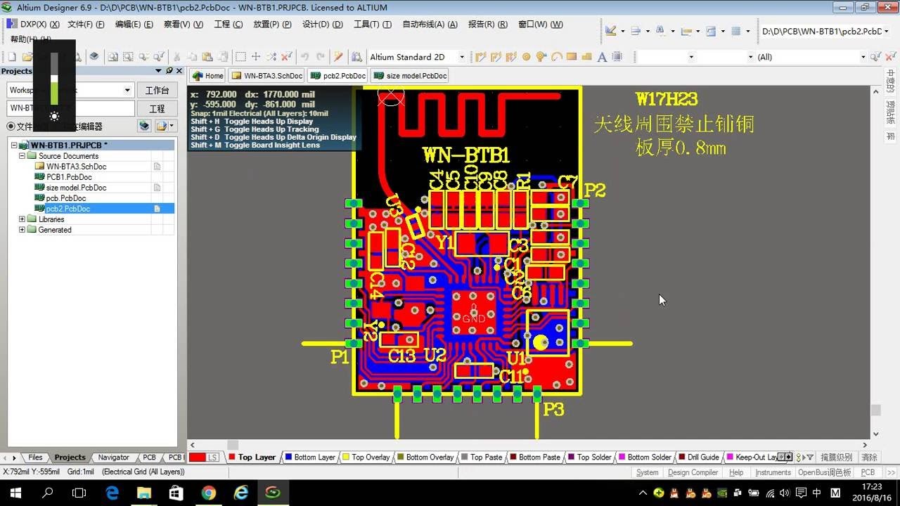
- PCB antenna looks cheap but there are too many shapes which I can not understand why they are like this. For example, There are two example.

This had been connected to ground one side. Why?
And this looks only wire. It just has a shape.
Where should I begin? What should I understand their shapes?


