Author Topic: Hakko 850 Hot Air Rework Rejuvenation  (Read 3996 times)

0 Members and 1 Guest are viewing this topic.

Offline wblockTopic starter

  • Regular Contributor
  • *
  • Posts: 239
  • Country: us
Hakko 850 Hot Air Rework Rejuvenation
« on: January 20, 2016, 11:10:24 pm »
Found a well-used, cheap Hakko 850 that appears to be the same version as the one in this thread: https://www.eevblog.com/forum/reviews/hakko-850-hot-air-rework-station/.  I can take pictures of this one if that would help.

Both the heater and air work, but the air pressure is really weak in comparison to an Aoyue Int852A+.  Ratings say the Hakko pumps 28 liters per minute, and the Aoyue only 23 liters per minute.  The Hakko did manage to desolder some SMT parts, but even at full throttle and with a narrow tip, there was little danger of blowing them away.

The pump (B1451) is powered directly from AC, controlled by a NEC AC03F triac.  The triac is good, according to the troubleshooting guide.  (Expected because the pump ran.)  The fan control potentiometer also measures okay (a 100K pot). There are no obvious air leaks anywhere, and the pump gets louder when those internal hoses are pinched.

It's hard to see where the air intake is, or if there is a filter.  There is a 1/4" opening on the underside of the white tank in this picture from that other thread: .
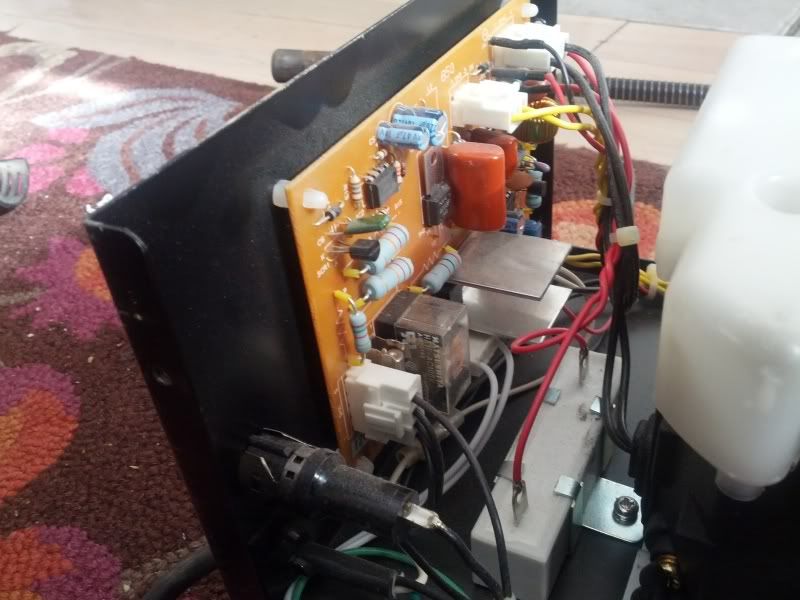
It still pumps air when that hole is covered, so if it is an intake, there are leaks elsewhere.

Is there an easy way to measure airflow without a special meter?

The other thread says not to open the pump unless you have replacement seals.  Are those gaskets or o-rings or something else?  Is that something I can make or find somewhere?
« Last Edit: January 21, 2016, 03:29:27 am by wblock »
 

Offline wblockTopic starter

  • Regular Contributor
  • *
  • Posts: 239
  • Country: us
Re: Hakko 850 Hot Air Rework Rejuvenation
« Reply #1 on: January 29, 2016, 11:28:39 pm »
Following up.  There do not seem to be any repair parts or even pictures of this pump on the web, so here goes.  This pump has diaphragms on each end, and the two ends are identical.  The white tank on top appears to be a muffler.  Removing the endcaps reveals a round plastic piece with two rubber discs that act as check valves.  There is a rubber gasket inside the end cap and a larger one under the check valve piece.  These are 1mm rubber.  Cutting replacements for these should not be too hard.  The rubber check valve discs might be more difficult.  They were about .7mm thick, and the flexibility might be important for them to work correctly.  Under the check valve piece is a diaphragm.  This is held onto the motor/solenoid with a small nut with both a lock washer and thread lock compound.  The diaphragm is made of several pieces, a molded rim, a thin disc, and some reinforcement at the center.

The output end on this particular pump was fine.  Taking apart the input side showed that the rim of the diaphragm was out of place, and this was due to a molding flaw in the housing.  When it was originally assembled, the diaphragm rim had not been fully pressed into place.  I sanded that edge down some and also rotated the diaphragm 180 degrees.  There were slight dust marks on the diaphragm here, so I think this was the leak.

All the removed plastic and rubber pieces were washed with soap and water, dried, then reassembled.  A quick test, and the pump is now much more powerful.
« Last Edit: January 29, 2016, 11:45:15 pm by wblock »


Share me

Digg  Facebook  SlashDot  Delicious  Technorati  Twitter  Google  Yahoo
Smf