Hey everyone,
First time here, so first off just a bit of context for the reason why I signed up: the company I work for recently decided to cut most of their US-based R&D; since I've had a lot less to do lately as a result, couldn't resist using the extra time to satisfy my curiosity and pull the cover off every single piece of equipment in the lab where I could get away without breaking a warranty or calibration sticker (or alternatively, where the warranty/calibration were obviously decades out of date). Looking inside and snapping some pics was fun for me, but it felt selfish to not share these peeks into weird and/or expensive and/or old test equipment with a ton of other people who also enjoy teardowns.
So there's a bunch coming, I've got at least 10 more posts worth of equipment (a few different models per manufacturer too). I'll be trying to analyze in reasonable depth what's inside and figure out the operation as much as possible from what I can see and explain how/why it works or was designed the way it is - after all that's the point of it all, not just looking at pretty pictures! (although there are some aesthetically nice bits here and there too) Some of this stuff may have service manuals which explain the details but honestly, I'm not interested in digging through endless search pages or bad scans, would much rather take the fun mental-puzzle approach instead...service manuals are left as an exercise to the reader

.
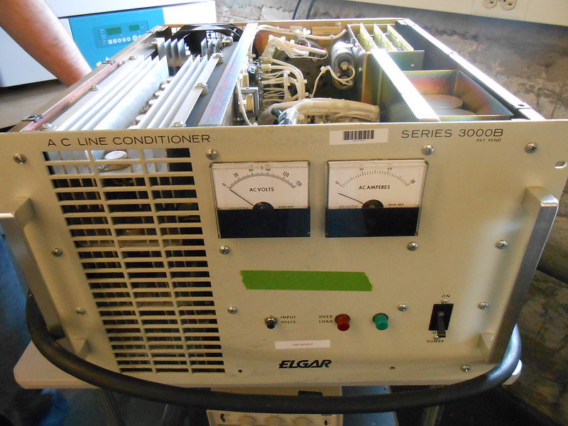
Anyways, first up is an Elgar 3000B AC line conditioner. This guy's a monster and everything about it looks like it's from the 70's. Seems it's supposed to "clean up" an AC line to get rid of noise / variation and flicker / etc. A couple of you may not realize that's a thing that's needed, but when you're in an industrial building and you can watch an incandescent lamp's brightness change on a 3-second cycle as some random giant load elsewhere cycles on and off, you can definitely appreciate the need for getting rid of AC line sag! Never actually seen this one used, as it was inherited from some other lab that used to occupy the same space.
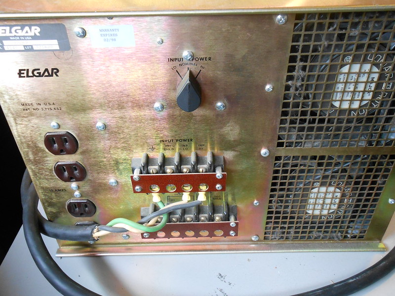
Here's the back panel:
...and here's the inside:

The highlights of this lovely industrial-sized doorstop are:
* A beautiful wiring job, with complex (but still neat-looking) harnesses, nicely routed and zip-tied.
* Ridiculous-sized components, from the transformer the size of my head which probably needs 3 people to lift it, to the switch as big as my foot, to the transistor array with 4 levels of 8 transistors each (32 total!) sharing the output load, with giant fans blowing across all of it.
Check out one of the 4 levels of transistors:

Here's that transformer:

Some caps hanging around in various places:


There's control boards off in the corner as well, with some nice obviously-hand-drawn traces:

Basically, the way I think this works is that it's just a giant linear regulator for the AC line, with a setpoint which moves in a clean sinewave shape. If you look inside a modern AC source (such as a Chroma or Kikisui), they'll create the AC output "from scratch": there'll be an AC-to-DC stage which creates a high-voltage DC supply from the incoming AC line, then an efficient switch-mode DC-to-AC stage. This Elgar, however, can't do this:
1. Appearance-wise, the design likely dates from the dawn of switch-mode power converters when that would've been difficult cutting-edge stuff.
2. There's no rectifiers that I can see for the AC-to-DC stage, unless a couple of the hidden levels of the heatsink are dedicated to that.
3. My intuition says that the capacitors in there aren't up to the bulk storage requirements of the DC bus; especially on something which can go to 10's of amps of output current according to the meter on the front.
4. There's no visible filtering for the output (even if you don't care about EMI, you've got to average that high-frequency PWM into a steady output voltage).
I'm also pretty sure it doesn't do an AC-to-DC then use the linear output stage to create the sinewave output from the steady DC bus, either: that would require the rectifiers which may or may not exist (see prev. point #2), lots of bulk capacitance (see prev. point #3), and most importantly, it would create massively unrealistic power dissipation in the output transistors, especially with imperfect-power-factor loads.
So here's my best guess: the AC line input comes in, gets stepped up slightly
above the desired output level by that massive transformer, gets some minor capacitive filtering to remove high-frequency noise, and then goes directly into the class-B output stage to be regulated down to the desired output. The step-up creates some overhead for the output regulation to work, and to have headroom so that the expected levels of sag in the input voltage won't cut into the output. Here's a drawing of what I mean:

The solid line is the incoming AC line, the dotted line is the regulated output, and the hashed section in between represents the voltage drop (and indirectly, the power dissipation) across the output transistors.
The variations in the incoming "dirty" AC line are just as likely to happen over multiple cycles than to happen over the course of a single cycle, but this illustrates the point best. The switch on the back selects between low/nominal/high line, and it runs straight to the transformer, so it's probably picking different primary windings with different step-up ratios:

It's worth noting that the downside of cleaning the AC line this way is that it's can't correct for
frequency variation without doing any serious energy storage. Maybe it uses those two large blue caps to do some short-term (<< 1 line cycle, a few degrees of phase) energy buffering and some of the power transistors control this. Doesn't seem particularly likely but still possible for all I know.
The control boards likely have a PLL or something which syncs to the incoming line frequency, and produces a clean sinewave of the right amplitude, which then drives the output transistors. There may also be some over-current protection as well. One of the capacitors or capacitor banks likely filters the output, to provide some low-impedance current sourcing when necessary for higher frequencies/faster dI/dt (aka, keeping output impedance low across a wider range of frequencies) than the transistors alone can provide.
Other notes:
* Control boards plug into an interesting "backplane-less backplane", where the card-edge connectors are screwed to the metal cage and connected to each other and the rest of the circuitry inside by individual wires, as part of that intricate wiring harness.
* Output transistors are 2N6259 150V 16A NPN (although the bottom 2 levels are probably PNP?); the low voltage rating is surprising, but then again if things are done just right maybe they never have to see the actual peak AC line voltage across them? Worst case is when there's a capacitive load on the output @ 0V, and the input is connected at the peak of the line...maybe there's some clever scheme to handle that case though. Or maybe the transistors are connected with pairs of 2 in series...this would make the base drive more complicated but it's doable with a resistor ladder.
* Resistors visible underneath each transistor are probably emitter resistors for current sharing.

* Control board base drive for the output transistor arrays probably comes from the 2 large-ish TO-3 guys at the back-left of the control boards...nothing else on the control boards looks even close to be up for driving the base current for 16 or 32 transistors with huge peak current capabilities and shitty beta. It's possible the output transistors are also arranged as Darlingtons, although in that case I'd expect half of them to be different lower-current/higher-beta models (maybe the 4 levels of transistors go: 8x NPN pre-driver, 8x NPN output, 8x PNP pre-driver, 8x PNP output?). Darlington arrangements feel most likely overall.
* The transformer surprised me by being from 1996 according to the label; this seems really late as the tech level in 1996 was so far beyond the level of this, and the style of everything here really screams 70's to me instead. May be an old design still manufactured long past its introduction.
I'll leave you all with a couple more shots of the nicely-made wiring harnesses:


