Back to where I was before mis-applying 130V to the 12V rail. Here's the list of symptoms I am seeing, so far:
1. An attenuated version of the the marker signal appears on the trigger output. It is most apparent at marker rates of 0.1, 0.5, and 1us and seems to be the 10MHz oscillator signal.
2. The .5us marker has a .6us period and doesn't change when adjusted according to the manual procedure.
3. The markers above 10us are not stable.
I am focused on first countdown board, where most of these signals are generated and comparing the signals and voltages I see with those on the schematic. Here's the first obvious issue, in the generation of the .5us marker:
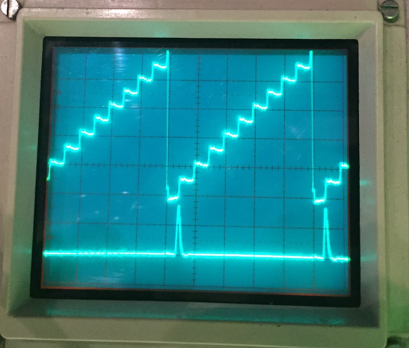
That's the ramp that creates the 0.5us pulse from five cycles of the 0.1us pulse. It should look like this:
Here's the circuit involved:
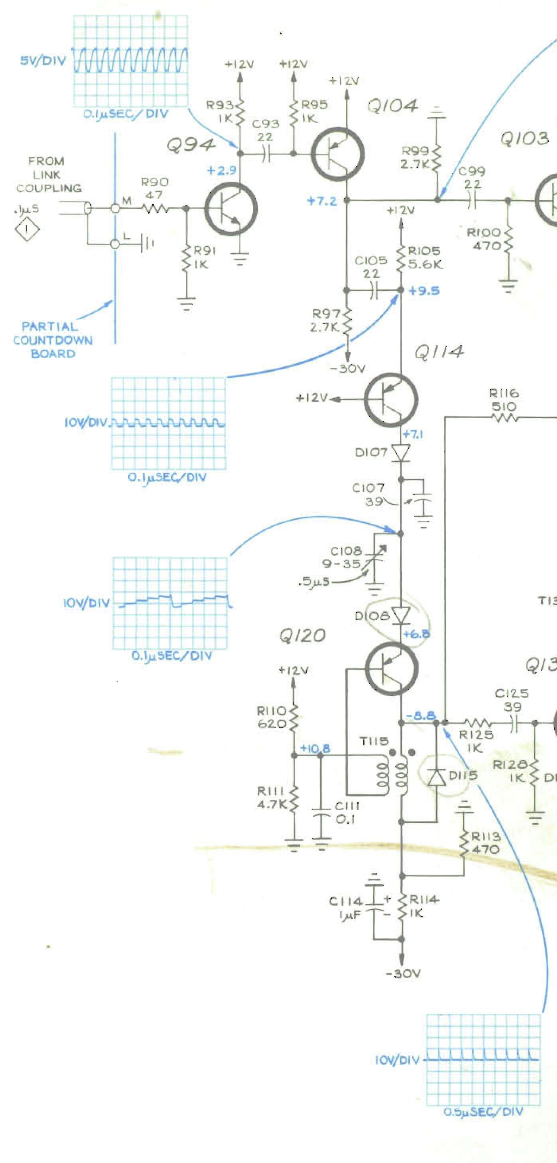
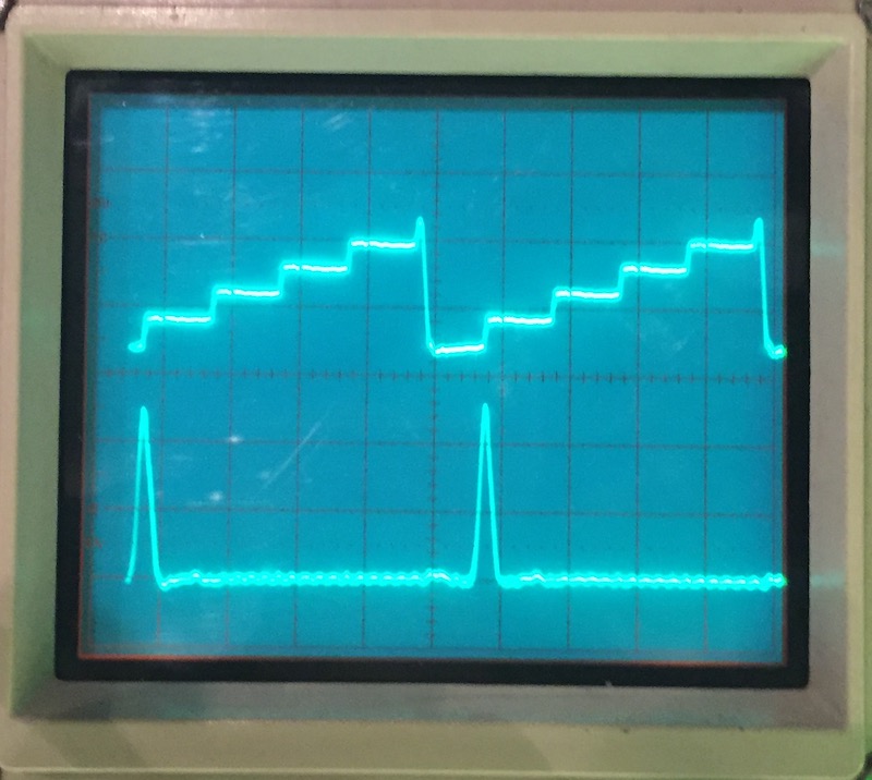
What appeared to be happening: Q114 wasn't dumping enough charge into C107 and C108 on each cycle, and so it took nine cycles to charge the capacitors up enough to trigger Q120. As I found in most other places on this board, the bias voltages were mostly out of spec. To increase current through Q114, I slowly lowered the resistance of R105. That brought the difference voltage across C105 back to specifcation and fixed the ramp (that's the first trace on second scope image above). The 0.5us pulse is now in spec (the second trace).
On to the next issue...


