I have a faulty Systron Donner M107 Precision DC Voltage Source, producing little to no output. I believe I have found the main fault area, but before I start fooling around in there, I'd like any advice on likely culprits.
Brief overview:-
The digital section encodes the 3 most significant digits (MSD), and the 3 least significant digits (LSD) of the programmed voltage setting into two independent (though synchronized) PWM signals, each having a duty cycle range of 0 to 999, and a frequency of 1.15KHz.
These signals are passed to the analog section via two pulse transformers driven by U20, and the PWM signals reconstituted by discrete flip-flops Q1/2 and Q3/4.
I believe the problem is that these flip-flops do not flip (i.e. they are flops

).
The outputs of U20 appear correct, as their duty cycles vary as expected with changes to the digit settings on the front panel. All power supplies are correct.
I'm not sure what the output of the pulse transformers should look like, so I don't know if they are bad, or the flip-flops have a problem. (or if I'm barking up the completely wrong tree here)
Further operation, of academic interest only, while the above problem remains:-
The PWM signals from Q1-Q4 are used to gate the LM299's 7v reference voltage via FETs Q5-Q8 into a summing junction at R22+R23, which is then filtered by C15-C20 et al, to provide the control voltage to the output amplifier. The LSD signals going into the summing junction have resistor values 1000 times higher than those for the MSD signals, so that the MSD PWM value contributes 1000 times as much as the LSD signal to the control voltage.
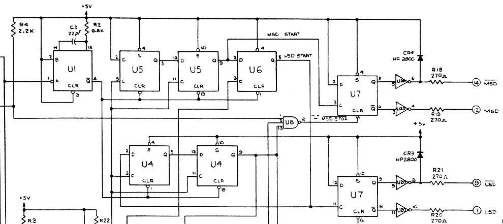
Section of digital schematic, showing U20, the pulse transformer driver.
Section of analog schematic, showing the flip-flops, voltage reference, gating circuitry, summing junction and filter.
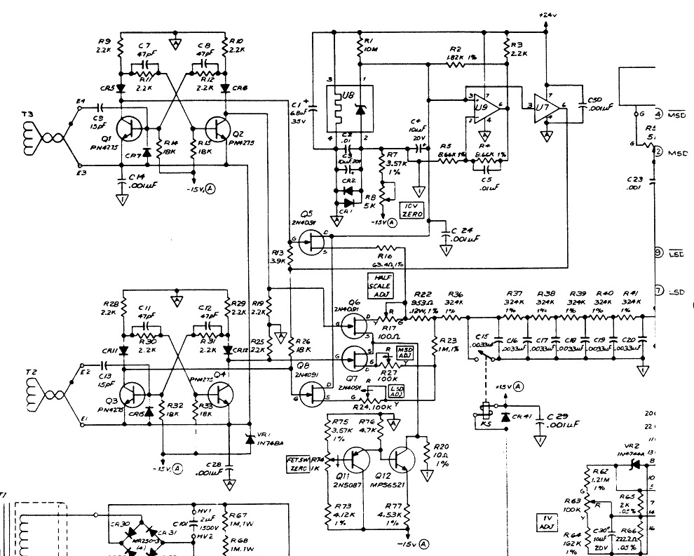
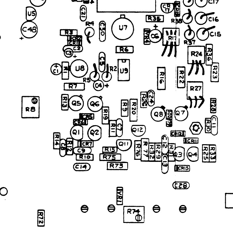
Photo of the above section of the analog board, showing the pulse transformers on the plate at the bottom.
The opto-couplers below them send range and polarity info to the analog section.

Parts overlay for the above.
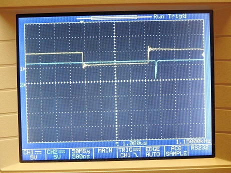
The top trace in the following CRO shots is the output at U20-6 (MSD) used as a sync/reference.
(The analog ground has been tied to digital ground/chassis earth to ease probing about)
The output of the MSD pulse transformer (LSD is similar, but shifted to the right a little)
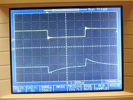
The collector of Q1, turned off briefly and trying to float up to +7v via R13, before it turns on again.

The collector of Q2, turned on briefly, pulling down from 0v to -10.5V. (All the emitters are at around -10.8v, due to VR1)

The collector of Q3, turned on briefly, pulling down from +7v via R26.
(Why isn't R13 pulling Q1 up to +7v even harder, since R13 is a lower value than R26?)
The collector of Q4, staying on at -10v.

The transistors I guess are prime suspects, but could all 4 be failed?
And since both FF's are not working, one would expect a common part to be at fault, but what?
Could failed FETs be dragging the FF's down?
I was hoping that putting this post together might help me see the problem, but no light bulbs here...
Any insights or advice would be greatly appreciated...
BTW: The service manual can be found at:-
https://elektrotanya.com/systron_donner_m107_precision_dc_voltage_source.pdf/download.html 


