Author Topic: Rewiring An Astatic G Stand With A 3 Pin Connector  (Read 451 times)

0 Members and 1 Guest are viewing this topic.

Offline OokpikTopic starter

  • Contributor
  • !
  • Posts: 38
  • Country: us
Rewiring An Astatic G Stand With A 3 Pin Connector
« on: August 16, 2023, 01:08:59 am »
I have an 3 pin Astatic G stand that I wish to add a 3 pin female connector to the end of the cord.

The cord has two white wire conductors with shield.

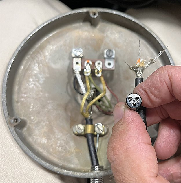
Which wires do I solder to pins 1 - 2 - 3 on the connector shown?

White wire with orange terminal dot to pin number ?

White plain wire to pin number ?

Shield wire to pin number ?

Any help in this matter would be greatly appreciated!  :)

Please see the photo below for additional info.


Offline DimitriP

  • Super Contributor
  • ***
  • Posts: 1376
  • Country: us
  • "Best practices" are best not practiced.© Dimitri
Re: Rewiring An Astatic G Stand With A 3 Pin Connector
« Reply #1 on: August 16, 2023, 01:48:26 am »
astatic  :-+
Below is a G-Stand diagram


It doesn't show the other end of the connector whihch is what you are looking for and it shows a red and white whire as well as a shield.

What-goes-where depends on what the radio expects.


« Last Edit: August 16, 2023, 01:51:08 am by DimitriP »
   If three 100  Ohm resistors are connected in parallel, and in series with a 200 Ohm resistor, how many resistors do you have? 
 

Offline OokpikTopic starter

  • Contributor
  • !
  • Posts: 38
  • Country: us
Re: Rewiring An Astatic G Stand With A 3 Pin Connector
« Reply #2 on: August 16, 2023, 04:10:05 am »
Thanks for the response!

I also found that schematic but like you stated, it does not include the information I am seeking.


Share me

Digg  Facebook  SlashDot  Delicious  Technorati  Twitter  Google  Yahoo
Smf