This scope was giving to me a year ago with the caveat that if the original owner needed it he could borrow it at anytime.
I used it but it did have problems, the position knobs in the amplifier are almost non responsive, and to get any signal to display I had to set the Voltage Divider to 5mV on top of using AC coupling because otherwise the bottom of the wave never goes bellow the center of the screen and it's totally unresponsive if no signal is present.

I have since purchased a Rigol so I had the monster (full rack depth) just sitting around and even if it wasn't terribly dirty I left it as I received it.
Yesterday I decided to restore it, I gave it a good clean, and feed my Rigol test signal (they both share the same earth), at 5mV per division using an x10 probe it barely gets to 0.3 divisions (x50mV) so about 15 mVpp when it was supposed to be 3Vpp, so it's reading 200 times low. But at least it's clean


Feeding it the 4 Vpp calibration signal built into the scope I get 1.7 divisions at 50mV per division (because of the x10 probe) that's 85mVpp so it's reading around 47 times low (not good because the error is greater at the lower voltage).

I have a known working single channel amplifier (not a very clean one, that I got on a recent auction) so I did swap it and the scope is happy. Signal is from the Rigol 3Vpp, x10 probe at 50mV/Div (so really 500mV per division) I get 6 divisions so the output is 3Vpp.

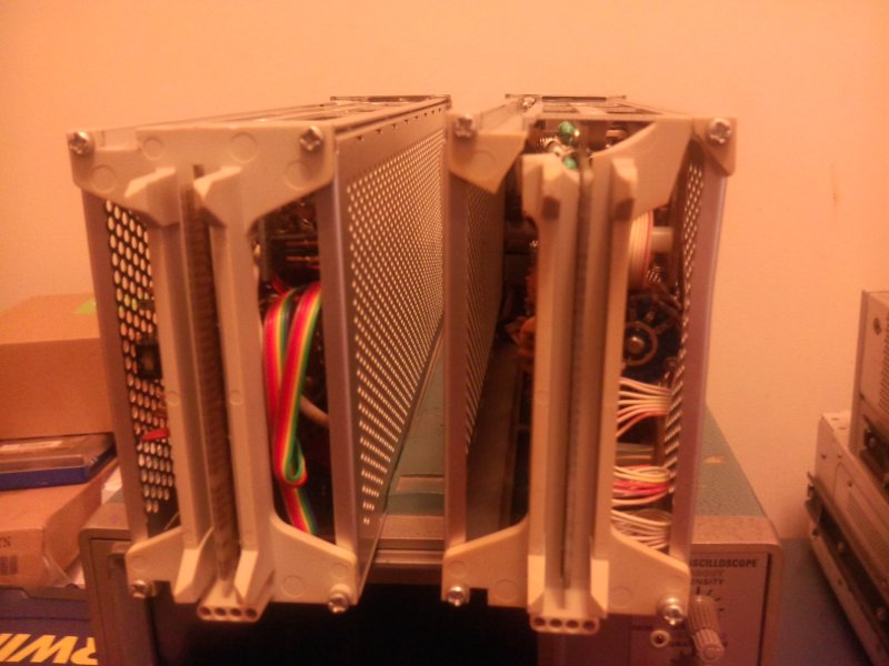
So the problem is the module so I took it out and examined it, and something doesn't look right, the back mounting assembly is broken and I didn't find any of the pieces inside the scope, so probably the plastic piece was broken a while back before I got the scope and probably before the previous owner got it, since it was given to him, and he told me that the scope always worked that way and he thought that's how it was supposed to work.

I took off the shield from one side of the module and noticed that a cable is detached. Maybe someone dropped the module and landed in the back, and the protection armature broke off and got into the board and cut the cable at its junction.

Not bad, since that should be an easy fix, but I took off the shield on the other side to see what was going on in there.

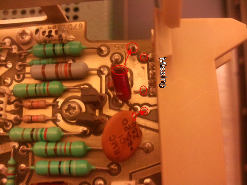
Broken off cap lead 0.01 uF, totally missing cap (same value) and broken off inductor 3.2 uH wrapped around a 10 Ohm resistor as a single component.

I do have plenty of spares, but they are all soldered to the board I'm working with (tek part number 108-084-00). And I don't have broken spare modules that I could take those from.
After looking at the schematic I realized it wasn't just an inductor, it's an inductor wrapped around a 10 ohm resistor.

The cap on one side is totally missing (not found in the enclosure either), the other cap has a broken lead (hard to see in the picture. And finally the LR (or RL) filter is broken with only one lead attached and part of the resistor lost.
So I need to replace C397, C398 and LR397
The caps are Tek part# 283-0002-00
Description: CAP.,FXD,CER DI:0.01UF,+80=20%,500V
So I found what I think is a good match on E14:
http://www.newark.com/vishay-bc-components/d103z25z5vf63l6r/ceramic-capacitor-0-01uf-50v-z5v/dp/80K9840Capacitance: 10000pF
+80%-20% tolerance
Disc
Radial
Dielectric Z5V
Lead Spacing 6.4mm
Operating Temperature Max 85°C
Operating Temperature Min -30°C
Voltage Rating 50V
@ $0.033 per, I got 100 for $3.30 total.
As for LR397 is Tek part# 108-0184-00
Description: COIL,RF:3.2UF(WOUND ON A 10 OHM,5%,0.5W RES)
I couldn't find a resistor wrapped with an inductor, let alone with a 3.2uF inductor.
So I'm planning to put a 10 Ohm, 5%, 1/4W carbon film resistor since that's what I have in hand, in parallel with this 3.3uH inductor from E14, bought 5 total @ $3 per.
http://www.newark.com/vishay-dale/ihd1eb3r3l/inductor-3-3uh-4a-axial-leaded/dp/53K4757Would that work? is the 0.1uF going to make a difference, or the 1/4W vs 1/2W for the resistor?
Hmm, element 14 is doing maintenance so the links are not working at the moment.