Author Topic: Rapco 1804M repair & 10MHz conversion/bodge (& teardown)  (Read 11460 times)

0 Members and 4 Guests are viewing this topic.

Offline grumpydocTopic starter

  • Super Contributor
  • ***
  • Posts: 2906
  • Country: gb
Rapco 1804M repair & 10MHz conversion/bodge (& teardown)
« on: August 11, 2012, 10:52:06 pm »
This story goes back a few months to a couple of Racal counter/timers that I had repaired for resale. I decided that I needed a decent reference to calibrate them against and bought one of the FE5680A Rubidium frequency standards - like the one Dave reviewed. Job done, I thought.

Then I got to thinking - I bought it on ebay, from Hong Kong, but that amounts to buying it from a bloke halfway around the world that I know nothing about. He says he's got a lab full of equipment but I have no proof of that or that he knows how to use any of it - how the heck do I know that this thing actually puts out an accurate 10MHz signal? The chances were, of course, that it was fine but I had no way of checking.

So, I spotted the 1804M for about the same money as I'd paid for the FE5680A and much cheaper than the Thunderbolt references that are kicking around on ebay - sorted :)

Except it broke :( and I couldn't find a 5MHz ocxo to fix it :( :(

I could find 10MHz ocxo's though, such as this one which was the right size, right pinout and similar spec to the original judging by the data sheet for the Rapco (the data sheet for the 8663 ocxo is here) - just the frequency was wrong.

So I decided to see if I could adapt the Rapco to a 10MHz oscillator. In any event it's a more useful output frequency and at least at some point the 1804M was available with 10MHz out as I have a few different revisions of the data sheet and some describe the unit as being 10MHz - not sure whether that was an option or a change to later units but as pretty much everything has standardised on a 10MHz reference clock it is much more useful than 5MHz.

I traced out the circuit to the block level rather than every individual component and was pleased to find it looked like this:


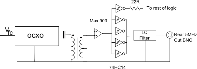
With a 10MHz ocxo fitted I could remove the 22R resistor and replace it with a 74HC74 to drop the 10MHz down to 5 - I'd get 10MHz out of the BNC - perhaps with a bit of tweaking to the LC filter used to shape it back to an approximate sine wave - and could feed 5MHz into the logic as before.

So I hunted around for a 74HC74 - lucked out on that one. I had just about every other family from a plain 7474, 74LS74 (lots of those) 74C74 (nearly used that) 74S74, 74F74 but not a "HC" - in the end I found a 74HC193 and used that. Slight overkill just for divide by 2 (it's a 4 bit presettable up/down binary counter) but it was on a junk board so free.

Made up a little bodge board using some tripad with the following on it


Here's a photo of the Rapco with the replacement oscillator and bodge board fitted (click on picture for large version).


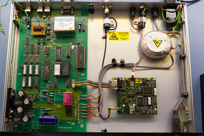
General quality of construction is very nice - if a little dated with through hole components and an 8-bit Z80 CPU.

The CPU is actually a Hitachi HD64180, there's also a M48T08 2k non-volatile SRAM/timer, a Z85230 serial chip and the AD569 16-bit monotonic D/A used to generate the oscillator control voltage. There are also a lot of Philips PLC18V8Z PALs for the glue logic and a trio of 74HC590 8 bit counters which presumably divide down the 5MHz and provide a count of clock "ticks" for the firmware.

You can also see the separate GPS reciever - this is a Trimble Sv6 (or probably the SV8 as mine does occasionally give info on 8 satellites).

The cable retainer is loose simply because I hadn't gotten round to putting it back.

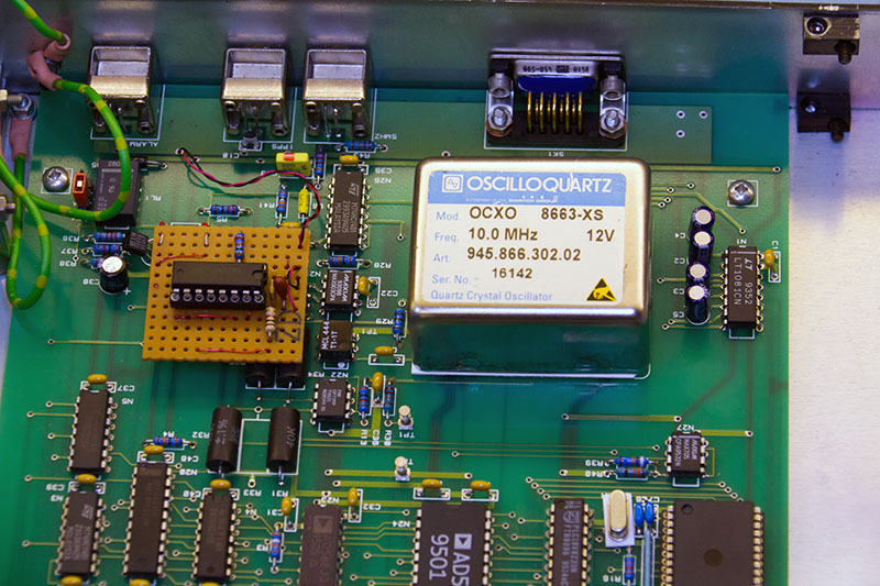
Here's a close up of the new ocxo and the bodge board with the 74HC193.


OK, so is it going to work? In the previous thread on the original ocxo Aurora mentioned that he'd been advised against changing the ocxo in the Rapco on the basis that the firmware could be quite fine-tuned to the oscillator characteristics. that is certainly possible but I figured if the control voltage range was about right and the slope was the same it was worth trying.

Initial impressions were good - 10MHz at the rear BNC at about 900mV p-p, a bit lower than it should be but it was enough to drive the external standard input on a Racal 1998 counter so "good enough" for the time being. Once it had a satellite fix it started the oscillator discipline routine. I confess I was a bit dubious but after 24 hours I was rewarded with this.


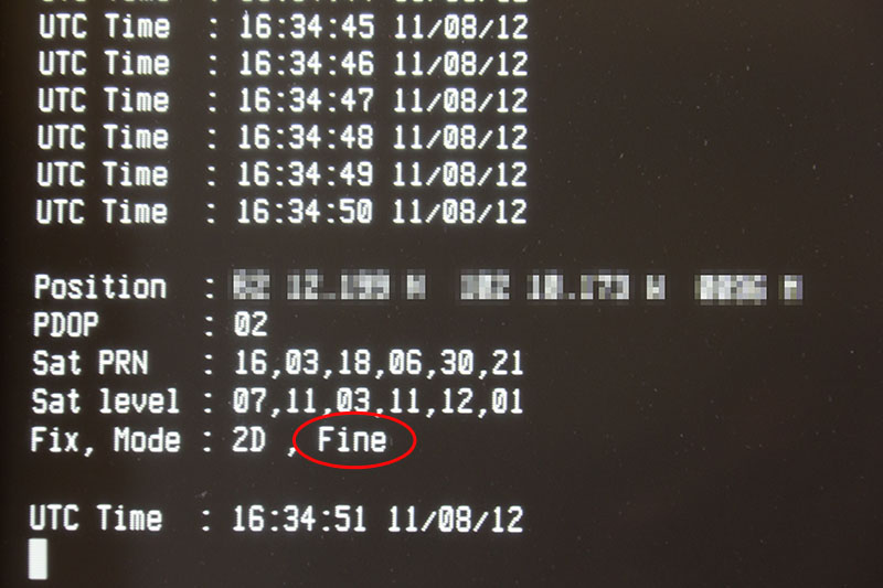
Once the Rapco reports "fine" control it means that the error is no more than 2 in 1010 - the 24hr average running with GPS control is supposed to be +/- 5 in 1011 with a +/- 3 in 1011 long term accuracy.

Actually that shot is a slight cheat as it was taken about 24 hours later - I didn't have chance to check the rubidium standard yesterday before it lost the fix and couldn't get it back long enough to achieve a "fine" control level for much of the day. So that photo was this morning when I had chance to check out the FE5680A.

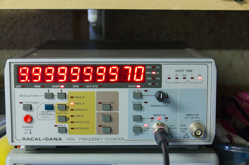
As a little diversion here's the Racal 1998 displaying the 10MHz output - for a "repair or spares" purchase from ebay it was surprisingly accurate - it has the 04E "high precision" Racal ocxo reference oscillator. For some reason the displays on these counters are hard to photograph - it doesn't bloom like that in reality.


Finally the FE5680A using the Rapco as the reference clock source. The most significant digit has overflowed so the display should be 10.000000000MHz!


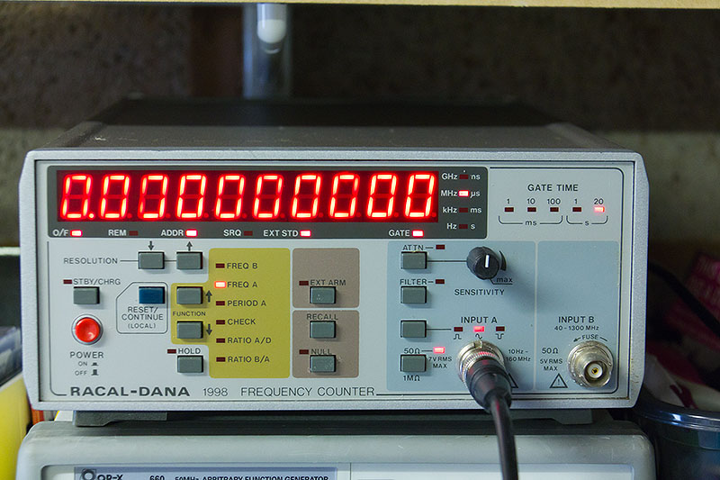
So I finally got to verify that the FE5680A was genuinely 10MHz plus or minus not very much at all - certainly good to 1-2 in 1010 and probably a bit better. And I'm finally happy with the Rapco (except I need a better antenna but that's another problem).

It turns out that these units are fairly easy to modify for a 10MHz ocxo should the original fail. It might not be the best mod purely to get 10MHz output though as the oscillators aren't the easiest of things to desolder without a vacuum desoldering tool. I think adding a PLL  between the Max 903 and the 74HC14 would be the best bet if the unit is otherwise working.

Edit: Added the bodge board circuit diagram for completeness.

« Last Edit: August 12, 2012, 01:44:20 pm by grumpydoc »
 

Offline DRT

  • Regular Contributor
  • *
  • Posts: 54
  • Country: gb
Re: Rapco 1804M repair & 10MHz conversion/bodge (& teardown)
« Reply #1 on: August 11, 2012, 11:53:32 pm »
As a fellow Rapco owner this is really interesting! I might try itmyself since 10MHz would be far more useful than 5MHz.

Have you ever experimented with the '1D' mode in the firmware? In this mode it seems to settle into 'Fine' control far more consistently, but I've not been able to positively confirm the timing performance. You can select it by typing "? SD1<CR> ?" - the fix status should then change to '1D'.
 

Offline grumpydocTopic starter

  • Super Contributor
  • ***
  • Posts: 2906
  • Country: gb
Re: Rapco 1804M repair & 10MHz conversion/bodge (& teardown)
« Reply #2 on: August 12, 2012, 07:45:21 am »
Quote
Have you ever experimented with the '1D' mode in the firmware?
No, although that's because I hadn't noticed it was there.

Quote
You can select it by typing "? SD1<CR> ?"
Ah, I thought "SD" did something else......

.....Yep, the later firmware manuals (2003 & 2009) say that the SDxx command sets an advance/delay timing on the 1Hz marker output to compensate for antenna cable length, looking back at the oldest manual I have (1998) it lists SDx (where x is 1 or 3) which sets timing/nav mode.

Not sure which manual is closest to the firmware version in my Rapco - certainly it behaves more like the documentation for the later versions. I'll try the SD command & see what happens.
 

Offline Dataforensics

  • Supporter
  • ****
  • Posts: 136
  • Country: gb
Re: Rapco 1804M repair & 10MHz conversion/bodge (& teardown)
« Reply #3 on: August 12, 2012, 01:48:28 pm »
Thanks from me too, I also have one of these bought as a toy from eBay.
Changing it to 10MHz would be a good mod for me too.
Now need to keep out a watch for an ocxo

Tony
 

Offline grumpydocTopic starter

  • Super Contributor
  • ***
  • Posts: 2906
  • Country: gb
Re: Rapco 1804M repair & 10MHz conversion/bodge (& teardown)
« Reply #4 on: August 12, 2012, 02:00:36 pm »
Quote
Now need to keep out a watch for an ocxo
No need - if you follow the link in my post the vendor has loads left and at £16 posted they're not exactly expensive. It arrived in about a week which I thought was pretty good from HK.

I have no affiliation with the vendor except as a satisfied customer.

Oh following DRT's suggestion I tried timing mode - mine seems to understand SD1/SD3 rather than the SDxx command - Haven't really run it for long but would have thought it should improve the oscillator control considerably. Not sure if timing is more accurate with 2 or more satellites.
 

Offline Fraser

  • Super Contributor
  • ***
  • Posts: 13265
  • Country: gb
Re: Rapco 1804M repair & 10MHz conversion/bodge (& teardown)
« Reply #5 on: August 12, 2012, 03:02:07 pm »
Thanks for this  :)

I am so pleased that the modification to 10MHz worked for you. My 5MHz Rapco is working and I was considering using a frequency doubler + buffer amplifier design to take it up to 10MHz. I have the parts to do it but not the time at the moment. Your use of a 10MHz OCXO has convinced me that the unit will accept a slightly different OCXO in terms of firmware control. Great news  :D

I have just bought the specified 10 MHz OCXO from RF-Buy, I have dealt with him before and he is a good seller as you you have found. I now have the option to change the OCXO if that suits my needs better.

With regard to the antenna that feed these Rapco units. You will no doubt have heard that the receiver is a little 'deaf' so a decent amplified GPS antenna is required. Many simple GPS antenna units designed for car use, and modern GPS receivers, contain a relatively low gain RF amplifier block fed from a ceramic patch. The Rapco was designed to be fed from a QFH antenna that contains a 26 to 38dB gain RF amplifier. Such antennas are commonly found in the professional GPS world and often look like ice-Cream cones  ;D My units came from China and were very reasonably priced considering what they contain. Professional GPS antennas are designed to have excellent sky coverage and to cope with RFI rich environments such as Cell towers. They also cope with long cable runs to the receiver. You can sometimes get away with a lower gain antenna if the feed cable losses are minimal. IMHO 26dB from a Patch type is about the minimum though.

The Rapco isn't so much 'deaf' (which sounds like a failing) but rather, designed for use in the professional world of higher performance L1 antennas. I recommend you either purchase an 'ice cream cone' professional antenna or add around 10dB RF gain to the antenna feed via an MMIC gain block.  The MAR or ERA series from Mini-Circuits work well. You will obviously need to include a power by-pass to maintain power to the integral Patch amplifier.

My 26dB professional antenna was bought from fluke.l for $30, via ebay and delivered to the UK. Pictures and datasheet attached

Kind Regards

Fraser
« Last Edit: August 12, 2012, 03:27:30 pm by Aurora »
If I have helped you please consider a donation : https://gofund.me/c86b0a2c
 

Offline Fraser

  • Super Contributor
  • ***
  • Posts: 13265
  • Country: gb
Re: Rapco 1804M repair & 10MHz conversion/bodge (& teardown)
« Reply #6 on: August 12, 2012, 03:19:18 pm »
I see fluke.l has some more L1 antenna's for sale:

http://www.ebay.co.uk/itm/Andrew-GPS-Timing-Reference-Antenna-20db-Gain-N-connect-/290646429424?pt=US_Ham_Radio_Receivers&hash=item43abe08ef0

Please be aware that they are lower gain amplifier models at only 20dB.It would be better to hunt down the 26dB gain models.

Regards

Fraser
If I have helped you please consider a donation : https://gofund.me/c86b0a2c
 

Offline grumpydocTopic starter

  • Super Contributor
  • ***
  • Posts: 2906
  • Country: gb
Re: Rapco 1804M repair & 10MHz conversion/bodge (& teardown)
« Reply #7 on: August 12, 2012, 04:13:11 pm »
Quote
Your use of a 10MHz OCXO has convinced me that the unit will accept a slightly different OCXO in terms of firmware control.

A bit more info on this:

The 8663 has a 0-10V control voltage with positive slope. I'm not sure what the HCD-66 is, as I can't find a datasheet for it, but the HCD-660 is 0.5-7V and I'm guessing the HCD-66 is the same (see below), the datasheet doesn't say what slope but I think we can assume positive.

Originally the Rapco was generating a VFC of 3.7V with a ADC value of about 0x78xx  (can't remember what the xx was). There seems to be an inverse relationship between the value in hex and the actual control voltage. With the new ocxo it has settled out to 0x48xx where xx is currently about 30 but it does jiggle up and down a bit with temperature. The control voltage is about 5V (I stopped registering the digits after the 5V - I just wanted to know it looked reasonable).

Note that both control voltages are close to the centre of their respective ranges.

Thus there is a bit of an incompatibility, there is less up frequency adjustment possible with the 8663 installed - obviously whether that is significant depends on whether you get a "good" one which hasn't drifted much or one which needs a VFC in the range 7-10V which the Rapco can't provide.

I don't think all would be lost in that situation though - while it doesn't look like  much can be done with the Vref for the DtoA itself - the reference voltage is generated by an AD588 and so fixed at +/- 5V. However I would think that the OP77FP (which you can see just to the left of/below the ocxo) is being used to buffer/level shift the DtoA output so it should be possible to tweak the gain of that stage.

Edit: - I note another potentially significant difference, though probably in a positive way. The adjustment range on the HCD-660 is given in the data sheet as ±5x10⁻⁷ whereas the 8663 datasheet seems to be saying ±3x10⁻⁷ - thus control might be slightly more precise with the latter ocxo.
« Last Edit: August 12, 2012, 04:43:03 pm by grumpydoc »
 

Offline DRT

  • Regular Contributor
  • *
  • Posts: 54
  • Country: gb
Re: Rapco 1804M repair & 10MHz conversion/bodge (& teardown)
« Reply #8 on: August 12, 2012, 04:18:59 pm »
I found that to get decent GPS performance with the Rapco I needed about 15dB gain on top of a standard active patch, so probably around 30-35 dB overall. The GPS also collapses very quickly with too much gain - I tried an additional 15dB gain block and it struggled.

The photos below show my somewhat bodged together UI for the Rapco. One mode shows time and date, the other shows GPS satellites in use and signal strengths.
 

Offline grumpydocTopic starter

  • Super Contributor
  • ***
  • Posts: 2906
  • Country: gb
Re: Rapco 1804M repair & 10MHz conversion/bodge (& teardown)
« Reply #9 on: August 12, 2012, 04:32:26 pm »
Quote
I see fluke.l has some more L1 antenna's for sale:
...
Please be aware that they are lower gain amplifier models at only 20dB.It would be better to hunt down the 26dB gain models.
It's tempting but I'm going to hack at a bit of other stuff on the to-do list first.

I see that there are also some 26dB units for sale for only a little more from "flyingbest" - not sure if that's one of rf-buy's pseudonyms but the two of them share a lab if the photo at the bottom of the listing is to be trusted  ;)
 

Offline Fraser

  • Super Contributor
  • ***
  • Posts: 13265
  • Country: gb
Re: Rapco 1804M repair & 10MHz conversion/bodge (& teardown)
« Reply #10 on: August 12, 2012, 04:58:50 pm »
flyingbest = RF-Buy  ;)

Fraser
If I have helped you please consider a donation : https://gofund.me/c86b0a2c
 

Offline Fraser

  • Super Contributor
  • ***
  • Posts: 13265
  • Country: gb
Re: Rapco 1804M repair & 10MHz conversion/bodge (& teardown)
« Reply #11 on: August 12, 2012, 05:17:20 pm »
WOW!.... I just took a look at the price of Trimble Thunderbolt GPSDO's. I paid around GBP80 each for my two, delivered to the UK from China. I see that they are almost twice that price now, and from the same sellers (flyingbest and fluke.l). Stock levels must be dropping or the sellers are getting greedy ?

Fraser
If I have helped you please consider a donation : https://gofund.me/c86b0a2c
 

Offline Dataforensics

  • Supporter
  • ****
  • Posts: 136
  • Country: gb
Re: Rapco 1804M repair & 10MHz conversion/bodge (& teardown)
« Reply #12 on: August 13, 2012, 01:48:32 am »
"No need - if you follow the link in my post"

Ah thanks for pointing out my poor eyesight :-)

I have ordered one from that Ebay seller.

Tony
 

Offline tnt

  • Regular Contributor
  • *
  • Posts: 241
Re: Rapco 1804M repair & 10MHz conversion/bodge (& teardown)
« Reply #13 on: August 13, 2012, 06:26:51 am »
It turns out that these units are fairly easy to modify for a 10MHz ocxo should the original fail. It might not be the best mod purely to get 10MHz output though as the oscillators aren't the easiest of things to desolder without a vacuum desoldering tool. I think adding a PLL  between the Max 903 and the 74HC14 would be the best bet if the unit is otherwise working.

Most PLL are going to have a horrible phase noise profile compared to the OCXO native output.
 

Offline grumpydocTopic starter

  • Super Contributor
  • ***
  • Posts: 2906
  • Country: gb
Re: Rapco 1804M repair & 10MHz conversion/bodge (& teardown)
« Reply #14 on: August 13, 2012, 08:27:02 am »
Quote
Most PLL are going to have a horrible phase noise profile compared to the OCXO native output.
A reasonable point - I suppose it depends what you want the output for. In my case it's just going to get fed into the external standard input on a counter or sig gen.

I suppose a PLL might be overkill for a simple frequency doubling as well.
« Last Edit: August 13, 2012, 08:35:25 am by grumpydoc »


Share me

Digg  Facebook  SlashDot  Delicious  Technorati  Twitter  Google  Yahoo
Smf